©
Panduit Corp. 201
4
OPERATION MANUAL
UPS003024024015
Page: 18 of 29
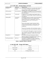
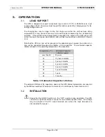
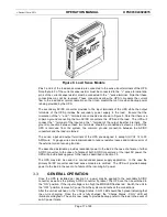
If the output of the UPS is overloaded the MOD status LED will flash red. Switch the unit to the
“
OFF
”
position and check that the load does not exceed to the maximum load power.
If AC power fails, the UPS will provide DC power to the load. The
“
Charge Status - CHG
”
LED
will flash red indicating the unit is being discharged. When the unit is fully discharged, the
“
Charge Status - CHG
”
LED will illuminate solid red. DC voltage will then be disconnected
from the load when it is no longer able to p24VDC. The unit will be accessible through
the WBI as described in Section 4 for approximately three minutes after it is no longer
supplying power to the load. When AC power is applied, the UPS will begin charging again
with the
“
Charge Status
”
LED blinking green.
STATUS VIA PC
3.4.
Status information and control of the UPS may be accessed by running a web browser on a PC
that is connected to the same network to which the UPS is connected. The UPS will be
assigned an IP address by the DHCP server running on the network. The network can be
configured to assign either a static or dynamic IP address to the UPS unit. Consult with the
network administrator as to how to determine the assigned IP address. See Section 4 for more
information on running the WBI.
STATUS VIA PLC
3.5.
Status information and control of the UPS may be accomplished through EthernetIP
communications.
EtherNet/IP™, better known as the Common Industrial Protocol (CIP™), was designed for use
in process control and industrial automation applications. CIP was designed to provide
consistent device access to eliminate the need for vendor specific software for configuration
and monitoring of individual devices. EDS files are installed using the “EDS Hardware
Installation Tool”.
If you are using RSLinx version 2.41.00, there are several EDS files that you must install before
programming the controller through RSLogix 5000 programming software. With newer versions
of RSLinx, this is not necessary. See the next page for the EDS files appropriate for each
CompactLogix controller. To install the EDS files:
1. Locate the appropriate EDS files. EDS files are available at either of the following
locations:
RSLogix 5000 software CD
http://www.panduit.com/support/up
s – Each EDS file has a specific location on
the web.
2. Copy all the files to a temporary subdirectory on your hard drive.
3. Use the EDS Hardware Installation tool to install the EDS files. This tool is installed
with RSLinx software under the RSLinxTools directory. It is also installed with
RSLogix 5000 software under the Utils directory.
a. Shutdown all applications that use RSLinx.
b. Shutdown RSLinx.
c. Start the EDS Hardware Installation Tool by selecting:
Start->Programs->Rockwell Software->Tools->EDS Hardware
Installation Tool.
d. Follow the on-screen instructions. Make sure to select
Register a directory
of EDS files
and point to the directory you saved all the above EDS files.

