
©
Panduit Corp. 201
4
OPERATION MANUAL
UPS003024024015
Page: 22 of 29
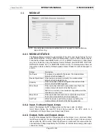
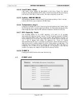
4.5.1. EVENT LOG
The event log records events pertaining to the automatic cell-balancing routine running
on the internal microcontroller. Since the time between cell-balancing events may
occur over relatively long time periods lasting days or even weeks, this allows the WBI
to record these events so that they may be reviewed at a later time. The event log
records when the automatic cell-balancing routine is activated or de-activated, when an
under or overvoltage condition is detected, as well as when any of the bleed resistors
are turned on or off. The stack voltage is recorded when the cell-balancing routine is
activated or de-activated and the cell voltage is recorded when an under or overvoltage
condition is detected, as well as when any of the bleed resistors are turned on or off. A
time stamp of the Elapsed Time is recorded with each of these events. The Event Log
can store a maximum of 1,000 events, which are stored in sequence. Older events are
deleted when the Event Log reaches its maximum capacity.
4.5.2. REFRESH
Pressing the Refresh button provides an explicit command to retrieve the latest
updates from the event log.
4.5.3. RETURN
Pressing the RETURN button will return the WBI to the Module page.
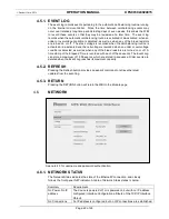
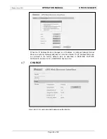
NETWORK
4.6.
See note 4.3 for username and password authentication.
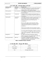
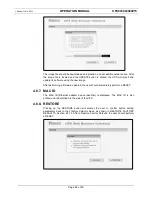
4.6.1. NETWORK STATUS
The Network Status indicates the state of the EthernetIP connection, and closely
follows the front panel NET indicator. A table of Network Status states is below.
Summary
Requirement
No Power, No IP
address
The device is powered off, or is powered on but with no IP address
configured (Interface Configuration attribute of the TCP/IP Interface
Object).
No Connections
An IP address is configured, but no CIP connections are established,


