
©
Panduit Corp. 201
4
OPERATION MANUAL
UPS003024024015
Page: 16 of 29
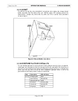
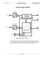
Figure 5: System Block Diagram
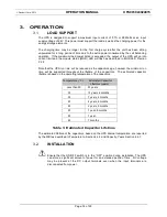
The UPS supports backup power for a load with redundant power supplies as shown in Figure
5. The primary AC/DC converter provides to the load through the provided optional load sense
module. The AC/DC converter is connected to pin 3 of the current sense resistor while pin 4 is
connected to the load. Figure 5 shows the pin numbering of the current sense resistor.
Zone Enclosure Wiring Diagram
+
5
-
6
Optional Load
Sense Module
UPS003LSM
2
4
24VDC
24VDC
120VAC
120VAC
Primary
Secondary
DC
120VAC
DC
Load
Ground
1
+
2 -
120VAC
1
3
UPS003024024015
7
G
ND
OUT
INP
4
-
3
+
SEN
CON
8 9
Dry
Contacts
24VDC
24VDC


