SMARTZONE UPS USER MANUAL
69
Press the left or right arrow on the “IN 02” line to select the meaning of the second input
dry contact (between IN pins 3 and 4 on the back of the UPS). The default is Close.
Press the left or right arrow on the “IN 03” line to select the meaning of the third input
dry contact (between IN pins 5 and 6 on the back of the UPS). The default is Close.
Press the left or right arrow on the “IN 04” line to select the meaning of the fourth input
dry contact (between IN pins 7 and 8 on the back of the UPS). The default is Close.
After making all the necessary changes on this page, press the “Save Config” button to
save the changes.
Press the down arrow to go to the next page. Press the up and over arrow to return to
the Advanced Setting Menu page.
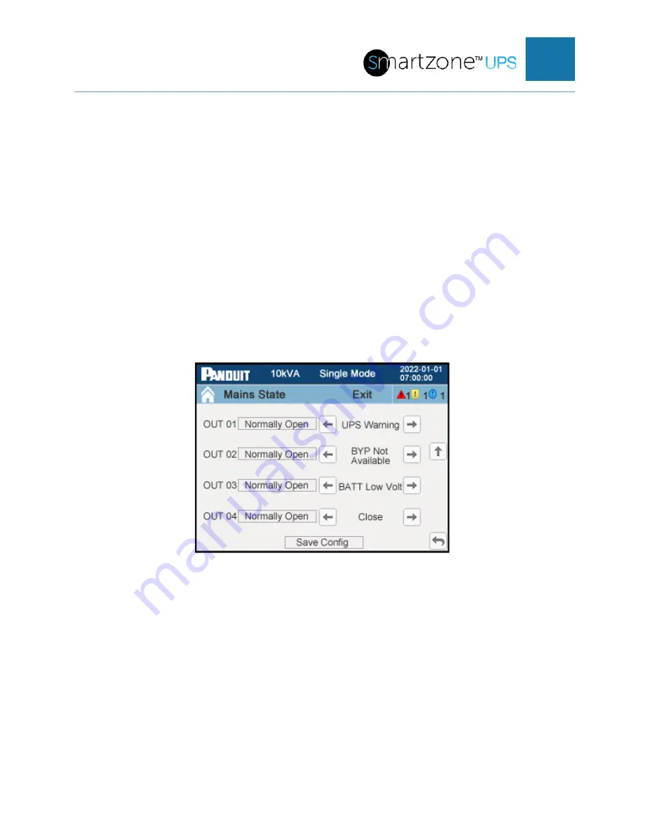
The second page allows the user to define the output dry contact points.
Figure 54: Dry Contact Setup Page 2 (3-Phase UPS)
Pressing the button field next to the “OUT 01” contact toggles the sense of this output
contact between “Normally Open” and “Normally Close”. Press the left or right arrow on
the “OUT 01” line to select the meaning (close, UPS Warning, Normal Mode, Battery
state, Bypass state, INV Overload, Fan Fault, Battery Fault, Battery Disconnected,
Battery Low Voltage, Main Abnormal, Bypass Not Available, EPO, Maintenance Bypass
Mode, Parallel Communications Fault, or ECO Mode) of the first output dry contact
(between OUT pins 1 and 2 on the back of the UPS).The default is Close. Close means
there is nothing assigned to this output dry contact.
Pressing on the button field next to the “OUT 2” contact toggles the sense of this output
contact between “Normally Open” and “Normally Close”. Press the left or right arrow on

