About Connectors
34
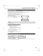
When settin
g
s menu - [Basic] - [Time & date] - [Auto adjustment time] is set to [Slave]
[Time Adjust Input] is availa
b
le and the time on the recorder is synchronized
w
ith the other devices.
15 minutes
b
efore or after the set [Activation time] if a signal output from another device is input to the Adjustment Time I/O, the time on the
recorder is set to the [Activation time].
Example:
W
hen the [Activation time] is set to 15:00
• A signal is received at 2:50:00 pm
→
Set to 3:00:00 pm
• A signal is received at 3:14:45 pm
→
Set to 3:00:00 pm
• A signal is received at 3:20:00 pm
→
Time is not adjusted.
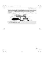
Connecting alarm e
q
uipment like the
b
uzzer and indicator to pins 15 to 1
8
sounds the
b
uzzer, lights the indicator and indicates operating status
w
hen a signal is output.
An example of HDD error output (pin 16) is sho
w
n
b
elo
w
.
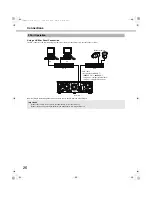
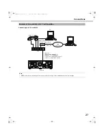
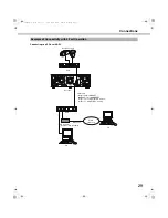
Auto Adjustment Time Function Connection 2
Important:
•
W
hen [Auto adjustment time] is set to [Slave], time adjustment is not performed during emergency recording and event recording.
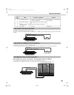
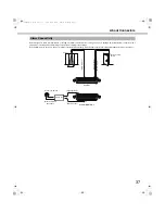
Connectivity for Control Output
20
13
(Signal gro
u
nd)
(Time adj
u
stment inp
u
t)
ALARM/CO
N
TROL
Front panel
LED monitor
o
u
tp
u
t
Ser
ies recording o
u
tp
u
t
Time adj
u
stment o
u
tp
u
t
T
emper
at
u
re w
ar
ning o
u
tp
u
t
System error o
u
tp
u
t
B
u
zz
er o
u
tp
u
t
Disk
Recording
Alar
m recording
Alar
m restore o
u
tp
u
t
Alar
m o
u
tp
u
t
Signal g
ro
u
nd
Time adj
u
stment inp
u
t
Ser
ies recording inp
u
t
Alar
m reset inp
u
t
Alar
m Inp
u
t
Sensor inp
u
t
Signal g
ro
u
nd
Terminal for other de
v
ices
16
13
(HDD error o
u
tp
u
t)
(Signal gro
u
nd)
Alarm eq
u
ipment
ALARM/CO
N
TROL
*Attached when necessary.
Relays etc.*
ND400_Basic.book 34 ページ 2008年4月8日 火曜日 午後3時59分

