background image

Usin

g

 the Front Panel for Operations

4

8

7

Select [YES] with the arrow buttons (left or ri

g

ht) and

then press the [SET] button.

8

Select the number of the extension unit where you
installed the HDD with the arrow buttons (up or down)
and press the [SET] button.

9

Select [YES] with the arrow buttons (left or ri

g

ht) and

then press the [SET] button.

All the HDDs installed in the extension unit are recognized for
recording.

Press the [SET] 

b

utton to return to the display format screen. 

10

Close the front cover of the extension unit and lock it by
li

g

htly pressin

g

 and turnin

g

 the key to the left. 

11

Check the available disk space.

Check the follo

w

ing content related to the HDD under [Disk

information] on the settings menu. Refer to the Setup
Instructions (PDF file) for more information.

HDD capacity

HDD remaining capacity

Hour meter

Disk operation mode

Date range of video recorded on the HDD

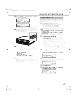
You can remove HDD units from the recorder 

w

hile it is in operation.

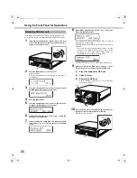
1

Insert the key (included) into the key hole and turn it
while pressin

g

 in 

g

ently to open the front cover.

2

Press the [USE] button for over 2 seconds. 

b

uzzer sounds.

Press the front panel 

b

uttons according to the directions on

the LCD.

3

Press the arrow buttons (up or down) on the front panel
until [HDD Operate] appears on the screen.

4

Press the [SET] button.

5

Press the arrow buttons (up or down) on the front panel
until [Remove HDD] appears on the screen.

6

Select [YES] with the arrow buttons (left or ri

g

ht) and

then press the [SET] button.

7

Select the HDD to be removed (Recorder: MAIN,
Extension unit: EXT) with the arrow buttons (up or down)
and then press the [SET] button.

8

Select the HDD to be removed with the arrow buttons (up
or down) and then press the [SET] button.

(2)

(1)

Removin

g

 HDDs

(1)

(2)

ND400_Basic.book  48 ページ  2008年4月8日 火曜日 午後3時59分

Содержание WJND400 - NETWORK DISK RECORDER

Страница 1: ...ect or operate this product please read these instructions carefully and save this manual for future use Network Disk Recorder Installation Guide Model No WJ ND400 1 2 3 4 5 6 7 8 9 ND400_Basic book 1 ページ 2008年4月8日 火曜日 午後3時59分 ...

Страница 2: ...rodukt till vilken denna deklaration hänvisar är i överensstämmelse med standarddokument eller andra normativa dokument som framställs i direktiv nr 2006 95 EC och 2004 108 EC Ilmoitamme yksinomaisella vastuullamme että tuote jota tämä ilmoitus koskee noudattaa seuraavia standardeja tai muita ohjeellisia asiakirjoja jotka noudattavat direktiivien 2006 95 EC ja 2004 108 EC säädöksiä Vi erklærer oss...

Страница 3: ...t harmful interference when the equipment is operated in a commercial environment This equipment generates uses and can radiate radio frequency energy and if not installed and used in accordance with the instruction manual may cause harmful interference to radio communications Operation of this equipment in a residential area is likely to cause harmful interference in which case the user will be r...

Страница 4: ...4 ND400_Basic book 4 ページ 2008年4月8日 火曜日 午後3時59分 ...

Страница 5: ...orded on the HDDs 17 Recording and Playing Images 18 Stable recording and playback of images 18 Setting Schedules 18 Event Functions 18 List of Functions 19 Setup Menu List 19 Network 20 Remote Operation 20 Network Security Function 20 SD Memory Recording 21 Maintenance Version Upgrade 21 Installation and Setup Getting Started 22 Setup Procedure 22 Setting up the Rack 23 Rack Mounting 23 Rack moun...

Страница 6: ...the Power 39 Turning Off the Power 39 During Recording 39 During Playback 39 Using the Front Panel for Operations 40 Basic Operations 40 Checking System Information 41 Checking the IP Address 42 Setting the IP Address 43 Configuring the Settings for Each Item 43 Setting and Canceling Key Lock 43 HDD Unit 44 Handling the HDD 45 Installing HDDs 46 Installing HDDs by unit 47 Removing HDDs 48 Removing...

Страница 7: ... the PC download the latest Adobe Reader from the Adobe web site and install it In this manual and on the screen the ND400 and the recorder are shown as WJ ND400 Refer to the readme txt file on the CD ROM bundled with the recorder for information about the versions and types of separately available software and cameras supported The following abbreviations are used in this document Microsoft Windo...

Страница 8: ...ities using a regularly updated anti virus program anti spyware program etc Protect your network against unauthorized access by restricting users to those who log in with an authorized user name and password Apply measures such as user authentication to protect your network against leakage or theft of information including image data authentication information user names and passwords alarm mail i...

Страница 9: ...recommended ambient temperature approx 25 ºC 77 ºF When hard disk drive trouble occurs replace it immediately Consult your dealer for servicing Hard disk drives are precise devices Do not leave them where the temperature is high and humid Do not touch the connector of the removable hard disk by hand directly to protect the hard disk drive from static electricity Take notice of the following for th...

Страница 10: ... that you make a note of your settings and save them This will help when you are required to change the system configuration or when unexpected trouble or failure occurs Distributing copying disassembling reverse compiling reverse engineering and also exporting in violation of export laws of the software provided with this product is expressly prohibited z MPEG 4 Visual patent portfolio license Th...

Страница 11: ...ts or blinks red The indicators display the status of the drives from HDD1 to HDD9 but if a system errors occur each indicator has the same display Front View 8 16 15 9 10 11 12 13 14 6 5 3 2 7 1 4 Blinks red System errors Blinks orange Temperature is too high or low Cooling fan stopped etc Blinks Alarm has occurred Lights Alarm output stopped Off Alarm is resolved or no alarm has occurred Lights ...

Страница 12: ...n off 16 Front cover Open to add or replace HDD units and to configure HDD operations Single RAID5 RAID6 Keep it closed and locked during normal operations Important When the HDD indicators light red in the RAID5 RAID6 mode quickly replace the HDD where the errors occurred Contact your dealer for information on replacing HDDs RAID5 mode Data cannot be recovered when two or more HDD indicators are ...

Страница 13: ...n mode Change The settings become effective after setting the RAID switch and turning on the Power switch while holding down the USE button to boot up Remember to hold down the USE button until the buzzer sounds Lights green HDD power On Formatted Blinks green HDD for playback only only for playback recording not possible Blinks orange Formatting HDD Lights red HDD format failed Off HDD power Off ...

Страница 14: ...ch and turning on the power while holding down the USE button to boot up 7 Removal knob Used when replacing the HDD units RAID5 mode The RAID5 mode can be used when more than three HDDs are installed RAID6 mode The RAID6 mode can be used when more than four HDDs are installed S SINGLE mode default R5 RAID5 mode R6 RAID6 mode Important The HDD operation mode cannot be changed once the system is ope...

Страница 15: ... connect the WJ HDE400 extension unit and the recorder with the connection cable provided with the extension unit 6 Client PC port PC Use to connect a PC 10BASE T 100BASE TX or 1000BASE T network 7 Camera port CAMERA Use to connect a camera 10BASE T 100BASE TX or 1000BASE T network 8 Signal GND terminal SIGNAL GND Use as a ground when the recorder s Signal GND terminal is connected to another devi...

Страница 16: ... only one area for each HDD 1 Normal Recording Area Area for recording except events Manual recording schedule recording SD memory data 2 Event Recording Area Area for recording when events occur Post event recording emergency recording 3 Pre event Recording Area Area for pre event recording 4 Copy area Area where copied data is saved Note The HDD provided in the recorder at the factory is initial...

Страница 17: ... volume when RAID5 mode enabled Theoretical volume HDD with smallest capacity in the unit x number of HDDs in the unit 1 Theoretical volume when RAID6 mode enabled Theoretical volume HDD with smallest capacity in the unit x number of HDDs in the unit 2 The capacity of the HDDs that are installed may be a few percents smaller The image and audio data recorded on the HDDs is encrypted The image and ...

Страница 18: ...mmand alarms For example if a camera sends a site alarm the recorder receives the alarm and an event occurs About event operations Event operations are the operations done when an event occurs Event operations include depending on the settings recording images recording logs sending external notification mail notification LED buzzers FTP transmission and others Here operations that send external n...

Страница 19: ...riod of time and are automatically transmitted to an FTP server A PC is notified of an alarm according to Panasonic alarm protocol settings When an event or error occurs a PC is automatically notified regarding event or error information according to the Panasonic alarm protocol settings Install the software option on the PC designated to receive and display event or error notification Refer to th...

Страница 20: ...orizontal and vertical position Zoom Zoom in out the image Focus Adjust the focus point of the image Brightness Adjust the lens iris brightness Preset operations Registers the preset position of camera and moves the camera to the registered preset positions Auto Select the camera s automatic mode function Network Security Function Important Network security settings vary depending on the LAN the r...

Страница 21: ... memory recording starts depends on the recording rate setting refer to the Setup Instructions PDF file Acquiring images stored on the SD memory card The images are acquired from the SD memory card and recorded on the HDD You can confirm if data is being acquired from the SD memory in the Status display SD memory data acquisition is done once an hour at 15 minutes past the hour You can upgrade the...

Страница 22: ...ettings Use the buttons on the recorder s front panel to do the network settings refer to the Setup Instructions PDF file 6 PC Network Settings Change the PC s network settings to match the recorder s settings refer to the Setup Instructions PDF file 7 Initialize HDDs To change HDD space management display disk configuration and initialize the HDD from the settings menu on the recorder as needed r...

Страница 23: ...ck Mounting EIA standard compliant product locally procured an EIA standard 19 rack depth 550 mm or more Remove rubber feet Handle for rack mounting bracket Rack mounting bracket Handle fixing screws for rack mounting bracket Washer Washer Rack mounting brackets provided Handle for rack mounting bracket Handle for rack mounting bracket Rack mounting bracket fixing screws provided Important Ensure ...

Страница 24: ... connection is poor the system may become unstable and unable to record images Keep the cables as short as possible Looped cables or large distances between pieces of equipment may cause malfunctions Also do not bend the cables more than 90º wind the cables in a coil 10 cm 3 94 in diameter Refer to the Setup Instructions PDF file to check the unit numbers of connected extension units Rack mounting...

Страница 25: ...PC and the Camera Important Use a LAN straight cable to connect the recorder and PCs via a hub Do not use a LAN cross cable to connect the recorder and PCs Using a LAN cross cable for continuous operation may result in incorrect display and playback because depending on the type of PC transmission may not be steady Connectivity Advantages Ports Used 1 port Operation Used when the PC and camera are...

Страница 26: ...o the PC from the client PC port 2 Port Operation Important Connect the camera to the camera port and the PC to the client PC port Connect the devices correctly Otherwise the transmission rate may be lowered HUB PC PC Recorder Network camera HUB LAN cable Not provided 10BASE T 100BASE TX 1 000BASE T category 5e straight NTSC model category 7 straight PAL model ND400_Basic book 26 ページ 2008年4月8日 火曜日...

Страница 27: ...istrator about router settings Example of Connectivity with 1 Port Operation PC WAN Internet PC ADSL line ADSL router Commercially available Network camera Recorder HUB LAN cable Not provided 10BASE T 100BASE TX 1 000BASE T category 5e straight NTSC model category 7 straight PAL model ND400_Basic book 27 ページ 2008年4月8日 火曜日 午後3時59分 ...

Страница 28: ...er area 1 HUB HUB LAN cable Not provided 10BASE T 100BASE TX 1 000BASE T category 5e straight NTSC model category 7 straight PAL model LAN cable Not provided 10BASE T 100BASE TX 1 000BASE T category 5e straight NTSC model category 7 straight PAL model ND400_Basic book 28 ページ 2008年4月8日 火曜日 午後3時59分 ...
Страница 29: ...2 Port Operation WAN Internet PC Recorder ADSL router Commercially available ADSL line PC Network camera HUB HUB LAN cable Not provided 10BASE T 100BASE TX 1 000BASE T category 5e straight NTSC model category 7 straight PAL model ND400_Basic book 29 ページ 2008年4月8日 火曜日 午後3時59分 ...

Страница 30: ...ecorder area 1 HUB HUB HUB LAN cable Not provided 10BASE T 100BASE TX 1 000BASE T category 5e straight NTSC model category 7 straight PAL model LAN cable Not provided 10BASE T 100BASE TX 1 000BASE T category 5e straight NTSC model category 7 straight PAL model ND400_Basic book 30 ページ 2008年4月8日 火曜日 午後3時59分 ...
Страница 31: ...res the included connection cable Secure the connection cables to the extension unit using the cable clamp provided If the connection is poor or the connector is not secure the system may become unstable and unable to record images 4 5 Attach a cable clamp for each connection cable Secure connection cable 3 2 1 Connection Cable provided with extension unit Network Disk Recorder Extension unit unit...

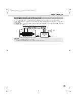
Страница 32: ...larm display Non voltage make contact input 5V pull up 150 kΩ 12 Emergency recording input Starting emergency recording signal input 13 Signal ground 14 Signal ground 15 Available disk space warning output Signal output for available disk space warning of the recording copy area Open collector output 24 V DC max 100 mA 16 HDD error output Signal output upon detection of a HDD error 17 Camera error...

Страница 33: ...tact input 5V pull up 150 kΩ 23 Outage detection input Start of outage processing according to the signal input 24 External recording mode switching input Changeover to the external recording mode 25 5 V output 5 V output 200 mA max Connectivity for Emergency Recording Connectivity for Switching to External Recording Auto Adjustment Time Function Connection 1 Pin Number Name Description of Operati...

Страница 34: ...s the indicator and indicates operating status when a signal is output An example of HDD error output pin 16 is shown below Auto Adjustment Time Function Connection 2 Important When Auto adjustment time is set to Slave time adjustment is not performed during emergency recording and event recording Connectivity for Control Output 20 13 Signal ground Time adjustment input ALARM CONTROL Front panel L...

Страница 35: ...er outage recovery completion output to the UPS and the recorder is then ready to turn off power Uninterruptible Power Supply UPS Connectivity Important Be sure to use a UPS that provides a sine wave output Do not use a UPS that provides a square wave Doing so may damage the recorder Uninterruptible Power Supply UPS 13 23 19 Power Outage recovery complection output Outage detection input Signal gr...

Страница 36: ...ettings Non voltage make contact input 5 V pull up 150 kΩ 2 Alarm input 18 3 Alarm input 19 4 Alarm input 20 5 Alarm input 20 6 Alarm input 22 7 Alarm input 23 8 Alarm input 24 9 Alarm input 1 10 Alarm input 2 11 Alarm input 3 12 Alarm input 4 13 Signal ground 14 Signal ground 15 Alarm input 25 Event action will be performed according to the settings Non voltage make contact input 5 V pull up 150 ...

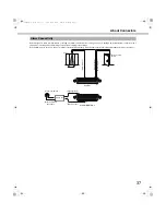
Страница 37: ...ording to the settings When alarm devices such as a buzzer or indicator are installed externally connect them to the Alarm output Alarm Control connector pin 21 Alarm Connectivity ALARM 21 9 Alarm equipment Relays etc ALARM CONTROL Alarm input 17 Signal ground Sensor Door security switch Alarm input 1 Alarm output Attached when necessary Signal ground 13 1 14 ND400_Basic book 37 ページ 2008年4月8日 火曜日 ...

Страница 38: ...ency recording input 100 ms or more L active Available disk space warning output From the time of the error occurrence until the time of the error output duration L active HDD error output From the time of the error occurrence until the time of the error output duration L active Camera error output From the time of the error occurrence until the time of the error output duration or the camera is r...

Страница 39: ...s PDF file 2 Turn off the POWER switch on the rear of the recorder after checking that the HDD indicators are off The operate indicator goes off Note Do not forget to start recording when you turn on the power 1 Click the STOP button on the HDD tab to stop playback refer to the Operating Instructions PDF file 2 Turn off the POWER switch on the rear of the recorder after checking that the HDD indic...

Страница 40: ...nformation IP Address Information Screen Displays settings related to the network connection You can check various network settings such as the IP address or subnet mask Refer to page 42 for more information IP Address Settings Screen You can configure settings related to the network connection You can set various network settings such as the IP address or subnet mask Refer to page 43 for more inf...

Страница 41: ...g system Check the settings by switching between screens using the following operations The LCD changes as follows when using the arrow buttons up or down Also pressing the arrow buttons left or right from PT 1 MAC address switches between the PT 2 and PT 3 screens Checking System Information SET ESC ND400_Basic book 41 ページ 2008年4月8日 火曜日 午後3時59分 ...

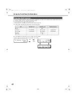
Страница 42: ...d under the client PC port PT 2 The following shows the initial default values for the recorder network settings Check the settings by switching between screens using the following operations The LCD changes as follows when using the arrow buttons up or down Checking the IP Address Item Camera port Client PC port Maintenance port DHCP OFF IP address 192 168 0 250 192 168 1 250 192 168 2 250 Subnet...

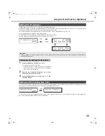
Страница 43: ... right the PT 2 and PT 3 screens are displayed and you can select other ports 2 Move the cursor using the arrow buttons up or down and enter values using up or down 3 Press the ESC button to move the cursor to and check the settings You can lock the buttons on the front panel to prevent them from being operated Press the SET button on the Key Lock Setting screen to lock the keys Keylock Enabled is...

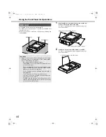
Страница 44: ...ormation on how to handle HDDs Also note the following precautions Do not subject them to vibration or impact To install HDDs use a torque driver and tighten the screws to the specified torque Before touching an HDD ground yourself against a metal object to eliminate any static electricity Always hold the HDDs by the sides when carrying them Use an anti static mat and wristband when installing or ...

Страница 45: ...tible HDDs Operation is only guaranteed with recommended HDDs All the HDDs must be the same model Even if the capacity is the same the space may be smaller by a few percent if the HDD models are different Always install the HDDs in order starting with HDD 1 Disk slots in order from 1 to 9 starting on the left In RAID5 or RAID6 modes do not change the position of the HDD after starting operation Re...

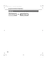
Страница 46: ...ts green after formatting is complete Preformatted HDDs are recognized for playback only In this case the HDD status indicator blinks green Follow the instructions from step 4 to use the HDD for recording Note The HDD status indicator may light green before blinking orange when an HDD is inserted 4 Press the USE button for over 2 seconds A buzzer sounds Press the front panel buttons according to t...

Страница 47: ...xtension unit according to steps 1 to 2 in Installing HDDs page 46 to install HDDs Repeat steps 1 to 2 to install multiple HDD units Note When installing HDD units each HDD unit must be recognized Follow Step 1 and 2 Additional HDD units will not be recognized while the first unit is being recognized 2 The HDD is automatically recognized While the HDD is being recognized the HDD status indicator b...

Страница 48: ...DD remaining capacity Hour meter Disk operation mode Date range of video recorded on the HDD You can remove HDD units from the recorder while it is in operation 1 Insert the key included into the key hole and turn it while pressing in gently to open the front cover 2 Press the USE button for over 2 seconds A buzzer sounds Press the front panel buttons according to the directions on the LCD 3 Press...

Страница 49: ...e knob on the HDD unit 2 Open the lever 3 Remove the HDD unit Remove the HDD carefully so you do not bump it be careful not to drop it 11 Close the front cover and lock it by lightly pressing and turning the key to the left Keep the key in a safe place 12 Check the disk information Check the following content related to the HDD under Disk information on the settings menu Refer to the Setup Instruc...

Страница 50: ... or down and then press the SET button 8 Select YES with the arrow buttons left or right and then press the SET button The extension unit stop process begins and all the HDD status indicators blink orange All the HDD status indicators go off once the stop process is complete If you stop the extension unit during recording recording switches to the HDD in another device Video is not recorded for a ...

Страница 51: ...gle mode as it is set up 1 Turn off the recorder Turn off the power according to Turning Off the Power page 39 2 Turn on any extension units first if any are connected 3 Insert the key included into the key hole and turn it while pressing in gently to open the front cover 4 Sets the operation mode with the RAID switch 5 Hold down the USE button and turn on the power to boot up The settings are ena...

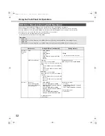
Страница 52: ...During recovery Recorder Extension unit LCD RAID 1 DOWN 1down RAID 2 DOWN 2down RAID 3 DOWN only while in RAID6 mode 3down Note Only extension units are shown HDD access indicator Lights red Errors have occurred on HDD Data can be recovered by replacing the HDD When in RAID5 mode the first HDD has errors When using RAID6 the first two HDDs have errors Blinks red Errors have occurred on HDD Data ca...

Страница 53: ...inserting the new HDD unit into the empty slot Press the HDD unit s removal knob down and lift the lever and then insert it all the way into the disk slot 1 Hook the HDD unit s tab securely on the HDD bay slot 2 Press the lever down and push the HDD unit until the removal knob clicks 3 The HDD is automatically recognized and recovery starts When recovery starts the HDD access indicator blinks oran...

Страница 54: ...nel for Operations 54 Press the SET button on the Manual Reboot screen to display the Manual Reboot ACCEPT screen Select YES and press the SET button to reboot Rebooting SET ND400_Basic book 54 ページ 2008年4月8日 火曜日 午後3時59分 ...

Страница 55: ... on the vents Extension unit is not recognized When an extension unit is connected Make sure that the cable provided with the extension unit is being used page 31 Make sure that the connection cable is not loose page 31 Was the extension unit turned on before the main unit Reboot the system and turn on the extension unit first page 39 If you are using a breaker or other system to turn on the power...

Страница 56: ...orange and red alternately even though recording or playback is not done Make sure that data is not recovered in RAID5 RAID6 mode page 52 The power cord insulation is damaged The power cord AC inlet or the power plug is damaged If you continue to use it a fire or an electric shock may occur Unplug the power cord immediately and refer servicing to qualified service personnel The power cord AC inlet...

Страница 57: ... installed 14 kg 30 9 lbs When 9 HDDs are installed 20 kg 44 15 lbs HDD Type function 3 5 HDD x 1 Up to 9 HDDs RAID5 mode available only when 3 or more HDDs are installed RAID6 mode available only when 4 or more HDDs are installed External storage High speed serial interface 1 5 Gbps theoretical value x5 Alarm Control connector Alarm input 8 16 1 Network error output 2 Alarm reset input 1 Emergenc...

Страница 58: ...llation Hard disk unit 1 pc Power cord NTSC model 1 pc Power cord PAL model 2 pcs Key 2 pcs Label 1 pc Rack mounting brackets 2 pcs Rack mounting brackets fixing screw 6 pcs Handle for rack mounting bracket 2 pcs Handle fixing screw for rack mounting bracket 4 pcs Washer 4 pcs HDD canister 8 pcs HDD fixing screw for HDD canister 48 pcs Standard Accessories ND400_Basic book 58 ページ 2008年4月8日 火曜日 午後3...

Страница 59: ...ecorded data 17 HDD replacement 16 45 53 HDD unit 14 16 44 High definition images 16 Host 20 Host authentication 20 HTTP port 20 42 43 HUB 25 I IP address 20 42 43 J JPEG 16 18 K Key Lock 43 L LAN 25 LGPL 10 Limit access 20 LINK ACT 12 LINK ACT1 12 LINK ACT2 12 Live monitoring 19 Live sequence display 19 M Maintenance 21 Maintenance port 42 Manual Reboot 54 Master 33 Mega pixel camera 16 MPEG 4 18...

Страница 60: ... batteries please take them to applicable collection points in accordance with your national legislation and the Directives 2002 96 EC and 2006 66 EC By disposing of these products and batteries correctly you will help to save valuable resources and prevent any potential negative effects on human health and the environment which could otherwise arise from inappropriate waste handling For more info...

Отзывы: