Major Operatin
g
Controls and Their Functions
15
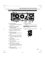
(1) Handle for Maintenance
Loosen the 5 scre
w
s indicated
b
y the triangles and grip these
handles to pull off the panel
w
hen replacing the fan or doing
other maintenance
w
ork.
(2) Alarm/Control connector [ALARM/
CONTROL], D-Sub 25 pin
Use to connect alarm devices (
b
uzzers or indicators),
external devices, control s
w
itches controlled
b
y the recorder.
(3) Alarm connector [ALARM], D-sub 25 pin
Use to connect alarm-related devices such as a sensor or a
door s
w
itch.
(4) Cable clamp fixin
g
holes
Install the ca
b
le clamp (provided
w
ith the extension unit) to
secure the connection ca
b
les.
For details refer to the manual for the extension unit (
W
J-
HDE400).
(5) External stora
g
e connector [EXT STORAGE]
Use to connect the (
W
J-HDE400) extension unit and the
recorder
w
ith the connection ca
b
le (provided
w
ith the
extension unit).
(6) Client PC port [PC]
Use to connect a PC, 10BASE-T, 100BASE-TX, or
1000BASE-T net
w
ork.
(7) Camera port [CAMERA]
Use to connect a camera, 10BASE-T, 100BASE-TX, or
1000BASE-T net
w
ork.
(8) Si
g
nal GND terminal [SIGNAL GND]
Use as a ground
w
hen the recorder
'
s Signal GND terminal is
connected to another device
'
s Signal GND terminal. Static or
other noise related pro
b
lems may occur if a ground is not
connected.
(9) Power cord Inlet [AC IN]
Connect the provided po
w
er cord here. The po
w
er plug is a
t
w
o prong plug
w
ith a ground terminal.
(10) Power switch [POWER]
Turns the po
w
er on. Press it again to turn the po
w
er off and
end operations.
Secure the po
w
er cord
w
ith the
b
race.
1
Lock the power cord in place by liftin
g
and latchin
g
the
brace.
Rear View
(9)
(10)
(8)
(7)
(6)
(5)
(1)(2) (3)
(1)
(4)
Usin
g
the Brace
Brace
ND400_Basic.book 15 ページ 2008年4月8日 火曜日 午後3時59分


