background image

Chapter 4

Settings — [POSITION] menu

ENGLISH - 79

[POSITION] menu

On the menu screen, select [POSITION] from the main menu, and select an item from the sub-

menu.

Refer to “Navigating through the menu” (

x

 page 65) for the operation of the menu screen.


f

After selecting the item, press 

asqw

 to set.

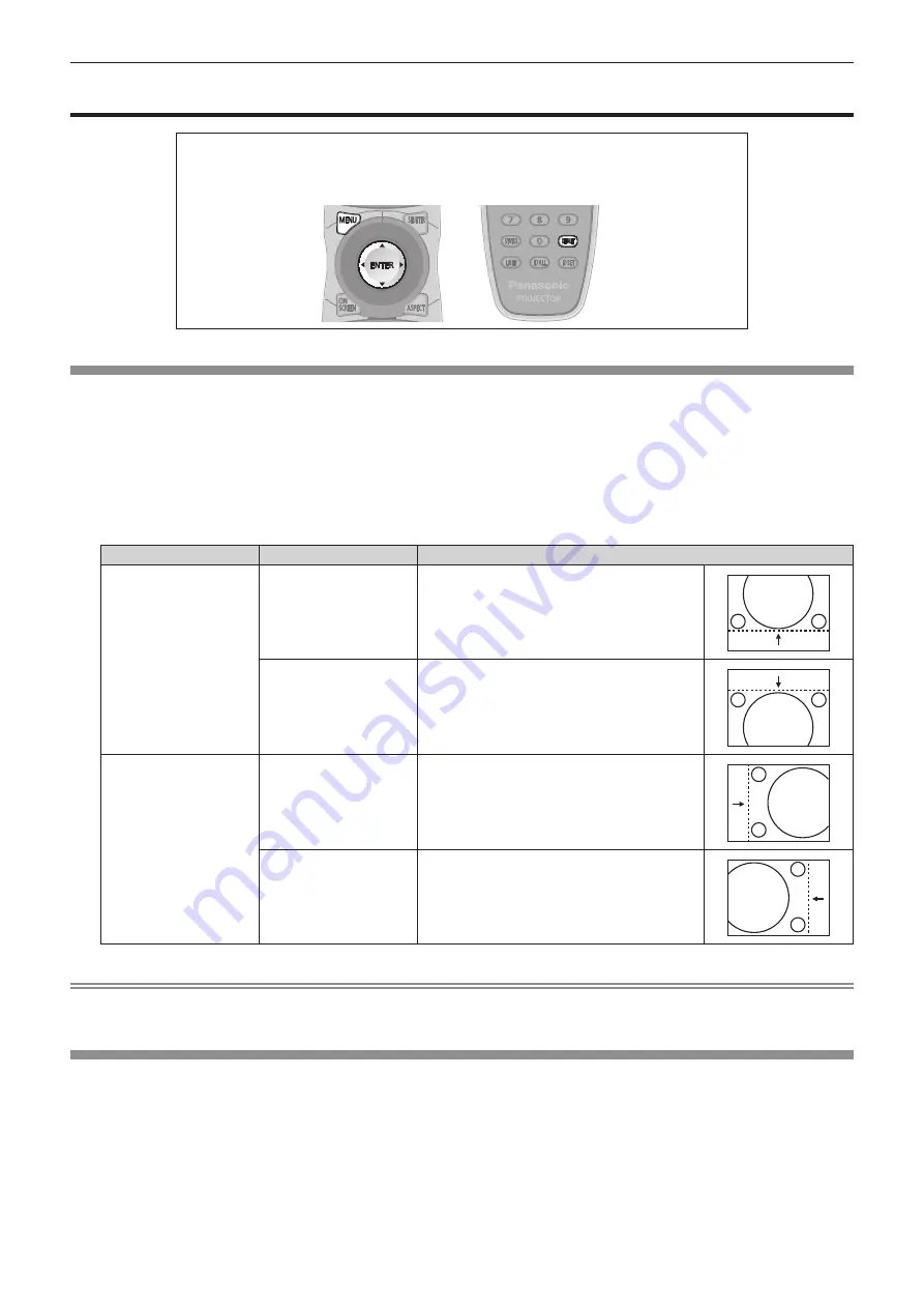
[SHIFT]

Move the image position vertically or horizontally if the image position projected on the screen is shifted even when the relative position of the 

projector and the screen is installed correctly.

1)  Press 

as

 to select [SHIFT].

2)  Press the <ENTER> button.


f

The 

[SHIFT]

 screen is displayed.

3)  Press 

asqw

 to adjust the position.

Orientation

Operation

Adjustment

Vertical (up and down) 

adjustment

Press the 

a

 button.

The image position moves up.

Press the 

s

 button.

The image position moves down.

Horizontal (right and left) 

adjustment

Press the 

w

 button.

The image position moves to the right.

Press the 

q

 button.

The image position moves to the left.

Note


f

For the portrait setting, image position is moved horizontally when “Vertical (up and down) adjustment” is made. Image position is moved 

vertically when “Horizontal (right and left) adjustment” is made.

[ASPECT]

You can switch the aspect ratio of the image.
The aspect ratio is switched within the screen range selected in [SCREEN SETTING]. Set [SCREEN SETTING] first. (

x

 page 97)

1)  Press 

as

 to select [ASPECT].

2)  Press 

qw

 or the <ENTER> button.


f

The 

[ASPECT]

 individual adjustment screen is displayed.

3)  Press 

qw

 to switch the item.


f

The items will switch each time you press the button.

Содержание PT-DZ13KU

Страница 1: ...ions carefully and save this manual for future use Before using your projector be sure to read Read this first x pages 2 to 9 TQBJ0521 DLPTM Projector Commercial Use Operating Instructions Functional...

Страница 2: ...k of electric shock to persons The exclamation point within an equilateral triangle is intended to alert the user to the presence of important operating and maintenance servicing instructions in the l...

Страница 3: ...lled and used in accordance with the instruction manual may cause harmful interference to radio communications Operation of this equipment in a residential area is likely to cause harmful interference...

Страница 4: ...sult f f Do not use plugs which are damaged or wall outlets which are coming loose from the wall Clean the power plug regularly to prevent it from becoming covered in dust Failure to observe this will...

Страница 5: ...tion adjustment and repair work please contact an Authorized Service Center Do not project an image with the lens cover of the projection lens optional attached Doing so can cause fire Do not allow me...

Страница 6: ...could result in loss of sight In this case do not rub your eyes Rinse with clean water and seek medical advice immediately Do not remove unspecified screws during the lamp unit replacement Doing so ca...

Страница 7: ...is being used Doing so can cause damage and burns to clothing f f Extremely strong light is emitted from the projector s lens Do not place objects in front of the lens while the projector is being us...

Страница 8: ...iate break every 30 to 60 minutes Watching for long periods of time may cause eye fatigue When preparing contents use contents properly created to be used for 3D This may cause eye fatigue or health p...

Страница 9: ...o pela bateria pode irritar a garganta danificar o lacre do inv lucro ou o vazamento provocar calor ruptura da blindagem e produzir fogo devido ao curto circuito dos terminais N o incinere nem aque a...

Страница 10: ...View and Crestron RoomView are registered trademarks of Crestron Electronics Inc Crestron Connected and Fusion RV are trademarks of Crestron Electronics Inc f f Adobe Flash Player is a trademark or re...

Страница 11: ...t mode is supported Improved cost performance in maintenance fee The extended life filter reduces maintenance costs Quick Steps For details refer to the corresponding pages 1 Set up the projector x pa...

Страница 12: ...ter 3 Basic Operations Switching on off the projector 52 Connecting the power cord 52 Power indicator 52 Switching on the projector 53 Making adjustments and selections 54 Switching off the projector...

Страница 13: ...OJECTOR SETUP menu 108 PROJECTOR ID 108 PROJECTION METHOD 108 COOLING CONDITION 109 HIGH ALTITUDE MODE 109 LAMP SELECT 109 LAMP RELAY 110 LAMP POWER 111 BRIGHTNESS CONTROL 111 STANDBY MODE 115 SCHEDUL...

Страница 14: ...acing the unit 159 Troubleshooting 163 Chapter 6 Appendix Technical information 166 PJLink protocol 166 Control commands via LAN 167 SERIAL IN SERIAL OUT terminal 169 REMOTE 2 IN terminal 173 Two wind...

Страница 15: ...ENGLISH 15 Chapter 1 Preparation This chapter describes things you need to know or check before using the projector...

Страница 16: ...m 4 593 or higher lower than 2 700 m 8 858 above sea level If you use the Smoke cut filter the operating environment temperature should be between 0 C 32 F and 35 C 95 F However it cannot be used at...

Страница 17: ...the projector bottom and the setting surface by inserting spacers metallic between them Screw holes for ceiling mount M6 Adjustable feet Clearance 5 mm 3 16 or longer Ensure the inflow of air into the...

Страница 18: ...companies will never ask for your password directly Do not divulge your password in case you receive such inquiries f f The connecting network must be secured by a firewall etc f f Set a password for...

Страница 19: ...ntingency r rComputer and external device connections f f When connecting a computer or an external device read this manual carefully regarding the use of power cords and shielded cables as well f f U...

Страница 20: ...f The model numbers of accessories are subject to change without prior notice Contents of the supplied CD ROM The contents of the supplied CD ROM are as follows Instruction list PDF Operating Instruc...

Страница 21: ...Ceilings ET PKD310S for Low Ceilings Projector ceiling mount bracket ET PAD310 Projector Frame for projectors ET PFD310 Replacement lamp unit ET LAD310A 1 pc ET LAD310AW 2 pcs Replacement lamp unit fo...

Страница 22: ...justment Adjust the focus to display the menu screen clearly You may also need to adjust the zoom and shift Refer to Adjusting the focus zoom and shift x page 56 for details 1 Press asqw to adjust the...

Страница 23: ...he ENTER button to proceed to the initial setting Initial setting screen setting Only for PT DZ13KU PT DS12KU PT DZ10KU Set the screen format aspect ratio and display position of the image After compl...

Страница 24: ...he remote control buttons The lights will go off when the remote control operation goes idle for 10 seconds 11 AUTO SETUP button Automatically adjusts the image display position while projecting the i...

Страница 25: ...e power indicator ON G STANDBY R will flash if the projector receives a remote control signal Projector body 1 2 3 4 5 6 7 6 8 8 10 9 12 14 15 16 14 13 11 17 14 SDI 1 2 Front Side Rear 18 14 Projectio...

Страница 26: ...tandby mode 3 VIDEO button Switches the input to VIDEO 4 RGB1 button Switches the input to RGB1 5 RGB2 button Switches the input to RGB2 6 DVI D button Switches the input to DVI D 7 HDMI button Switch...

Страница 27: ...l This is the terminal to input SDI signals Only for PT DZ13KU PT DS12KU 7 HDMI IN terminal This is the terminal to input HDMI signals 8 RGB 1 IN R PR G Y B PB C SYNC HD VD terminal This is a terminal...

Страница 28: ...a projector by pressing the ID ALL button on the remote control even if you do not know the projector ID How to set 1 Press the ID SET button on the remote control 2 Within five seconds press the two...

Страница 29: ...ntrol is effective even in places where an obstacle stands in the light path or where devices are susceptible to outside light Connecting terminals Connecting to a second projector M3 stereo mini jack...

Страница 30: ...30 ENGLISH Chapter 2 Getting Started This chapter describes things you need to do before using the projector such as the setup and connections...

Страница 31: ...ar Using the translucent screen Setting on a desk floor and projecting forward Menu item Method Menu item Method PROJECTION METHOD REAR CEILING PROJECTION METHOD FRONT FLOOR COOLING CONDITION CEILING...

Страница 32: ...n distances to install the projector Image size and image position can be adjusted in accordance with the screen size and screen position SD L LW LT L1 L1 L LW LT SW SH SH SW Projection screen Screen...

Страница 33: ...KEYSTONE and CURVED used together Only for CURVED Vertical keystone correction angle Horizontal keystone correction angle Vertical keystone correction angle Horizontal keystone correction angle Min va...

Страница 34: ...5LE5 22 15 8 8 1 5 3 7 0 9 2 2 ET D75LE6 28 15 10 10 1 2 3 0 0 7 1 7 ET D75LE8 45 40 20 15 0 2 0 3 0 1 0 2 ET D75LE10 40 40 20 15 0 9 2 0 0 5 1 1 ET D75LE20 40 40 20 15 0 7 1 3 0 4 0 7 ET D75LE30 45 4...

Страница 35: ...40 01 63 70 63 42 119 19 8 00 9 58 12 70 500 6 731 10 770 14 85 19 84 19 94 29 92 29 93 50 03 50 04 79 65 79 37 149 08 10 01 11 99 15 24 600 8 077 12 923 17 83 23 82 23 94 35 93 35 94 60 06 60 07 95 6...

Страница 36: ...0 29 12 33 15 24 600 7 472 13 283 18 33 24 49 24 61 36 93 36 94 61 73 61 74 98 26 97 98 183 95 12 36 14 81 25 40 1000 12 453 22 138 30 60 40 88 41 07 61 62 61 63 102 97 102 98 163 83 163 56 20 64 24 7...

Страница 37: ...1 34 13 58 15 24 600 9 144 12 192 20 20 26 98 27 12 40 69 40 70 68 01 68 02 108 24 107 96 202 65 13 62 16 32 25 40 1000 15 240 20 320 33 71 45 04 45 25 67 88 67 90 113 43 113 44 180 46 180 20 22 74 27...

Страница 38: ...3 23 10 29 12 33 15 24 600 9 144 12 192 18 33 24 49 24 61 36 93 36 94 61 73 61 74 98 26 97 98 183 95 12 36 14 81 25 40 1000 15 240 20 320 30 60 40 88 41 07 61 62 61 63 102 97 102 98 163 83 163 56 20 6...

Страница 39: ...22 13 43 15 24 600 7 472 13 283 19 97 26 69 26 82 40 24 40 25 67 26 67 26 107 04 106 77 200 41 13 47 16 14 25 40 1000 12 453 22 138 33 34 44 54 44 75 67 13 67 15 112 18 112 18 178 47 178 20 22 49 26 9...

Страница 40: ...71 16 11 49 13 78 15 24 600 7 472 13 283 20 48 27 36 27 49 41 25 41 26 68 95 68 96 109 74 109 47 205 46 13 80 16 55 25 40 1000 12 453 22 138 34 18 45 67 45 88 68 83 68 84 115 00 115 01 182 97 182 70 2...

Страница 41: ...14 08 16 88 15 24 600 9 144 12 192 25 09 33 52 33 68 50 53 50 54 84 45 84 45 134 38 134 11 251 62 16 91 20 27 25 40 1000 15 240 20 320 41 86 55 93 56 18 84 29 84 30 140 83 140 83 224 03 223 77 28 22...

Страница 42: ...Max LT L 4 0591 x SD 0 1216 3 3 to 5 5 1 4 3 Min LW L 2 6772 x SD 0 0958 Max LT L 4 4724 x SD 0 1216 ET D75LE4 4 6 to 7 4 1 16 10 Min LW L 3 9488 x SD 0 1158 Max LT L 6 2795 x SD 0 1013 4 6 to 7 4 1...

Страница 43: ...r r Zoom lens Projection lens Model No Throw ratio Aspect ratio Projection distance L formula ET D75LE1 1 5 to 2 0 1 4 3 Min LW L 1 2087 x SD 0 0760 Max LT L 1 6142 x SD 0 1004 16 9 Min LW L 1 3150 x...

Страница 44: ...ET D75LE1 1 5 to 2 0 1 16 9 Min LW L 1 3504 x SD 0 0760 Max LT L 1 8031 x SD 0 1004 2 0 to 2 7 1 4 3 Min LW L 1 6496 x SD 0 0760 Max LT L 2 2047 x SD 0 1004 ET D75LE2 2 1 to 3 1 1 16 9 Min LW L 1 811...

Страница 45: ...D 0 0835 1 0 1 4 3 L 0 8504 x SD 0 0835 ET D75LE50 0 8 1 16 9 L 0 6925 x SD 0 0713 1 0 1 4 3 L 0 8479 x SD 0 0713 Adjusting adjustable feet Install the projector on a flat surface so that the front of...

Страница 46: ...ft of LOCK and turn clockwise until it clicks Fig 1 2 Secure the projection lens with the lens fixing screw supplied Fig 2 f f Use a Phillips screwdriver to secure it in the screw hole A to the right...

Страница 47: ...Started Attaching removing the projection lens optional ENGLISH 47 Attention f f Store the removed projection lens where it will be free from vibration and impact f f Store the removed lens fixing scr...

Страница 48: ...f Video signals containing too much jitter may cause the images on the screen to randomly wobble or wafture In this case a time base corrector TBC must be connected f f The projector accepts video si...

Страница 49: ...ctor TBC between the projector and the VCR f f If nonstandard burst signals are connected the image may be distorted In such case connect the time base corrector TBC between the projector and the exte...

Страница 50: ...T DS12KU f f When an unsteady signal is connected an error in signal detection may occur In such a case use the PICTURE menu SYSTEM SELECTOR to switch to a system that matches the signal format Connec...

Страница 51: ...ENGLISH 51 Chapter 3 Basic Operations This chapter describes basic operations to start with...

Страница 52: ...irm that the MAIN POWER switch on the side of the projector body is on the OFF side and remove the power plug from the outlet 2 Remove the power cord connector from the AC IN terminal of the projector...

Страница 53: ...e standby mode 4 Press the power on b button f f The power indicator ON G STANDBY R lights in green and the image is soon projected on the screen Attention f f Using the projector while the lens cover...

Страница 54: ...D VIDEO HDMI SDI 1 2 buttons to select the input signal SDI input is only for PT DZ13KU PT DS12KU PT DZ10KU 4 Adjust the front back and sideway tilt of the projector with the adjustable feet x page 4...

Страница 55: ...n the projector again f f The projector consumes power even when the power standby v button is pressed and the projector is switched off if the main power of the projector is on When the PROJECTOR SET...

Страница 56: ...ts zoom f f SHIFT button Adjusts shift 2 Select each item and press asqw to adjust it Caution During the lens shift operation do not insert your hand in any opening around the lens Your hand may be ca...

Страница 57: ...Adjustment range by the lens position shift optical shift Perform the lens position shift within the adjustment range The focus may change when the lens position is shifted out of the adjustment range...

Страница 58: ...dotted arrow line the upper side of the screen focus surface will tilt inwards and the lower side will tilt outwards as shown in the example Projection lens Image forming surface Screen focus surface...

Страница 59: ...e c Rotate counterclockwise Rotate counterclockwise 1 Press the FOCUS button on the remote control or the LENS button on the control panel to display the FOCUS adjustment menu 2 Press s to shift the f...

Страница 60: ...reset the screen position of the projected image on the screen surface back to an optimal state 7 Perform focus adjustment again near the center of the screen and if it is still not enough fine tune...

Страница 61: ...te f f The power indicator ON G STANDBY R will flash slowly in green while the shutter is closed f f You can set the speed of shutter opening closing via the DISPLAY OPTION menu SHUTTER SETTING Using...

Страница 62: ...US button f f The STATUS screen is displayed ENTER MENU RGB2 XGA60 A8 48 36kHz 60 03Hz 140h 68h ON 69h ON 27 C 80 F 33 C 92 F 33 C 92 F SEND STATUS VIA E MAIL CHANGE EXIT STATUS INPUT SIGNAL NAME SIGN...

Страница 63: ...stment may not be performed properly even for an RGB signal that can use automatic setup INCOMPLETE may appear or adjustment may not be finished properly even if COMPLETE appears Using the Function bu...

Страница 64: ...64 ENGLISH Chapter 4 Settings This chapter describes the settings and adjustments you can make using the on screen menu...

Страница 65: ...LANGUAGE DISPLAY OPTION 3D SETTINGS PROJECTOR SETUP TEST PATTERN SIGNAL LIST SECURITY NETWORK MENU SELECT SUB MENU P IN P 2 Press as to select an item from the main menu f f The selected item is highl...

Страница 66: ...menu ON SCREEN DISPLAY OSD DESIGN The selected item is displayed with the yellow cursor by the factory default f f In the portrait setting the menu is displayed sideways Resetting adjustment values to...

Страница 67: ...0 72 TINT 0 72 COLOR TEMPERATURE DEFAULT 72 GAMMA DEFAULT 74 SYSTEM DAYLIGHT VIEW OFF 75 SHARPNESS 6 75 NOISE REDUCTION OFF 76 DYNAMIC IRIS 2 76 SYSTEM SELECTOR YPBPR 1 77 1 Depends on the signal inpu...

Страница 68: ...1 3D SIMUL INPUT SETTING 92 3D INPUT FORMAT AUTO 1 92 LEFT RIGHT SWAP NORMAL 93 3D COLOR MATCHING SHARED 2D 3D 93 3D PICTURE BALANCE 93 DARK TIME SETTING 1 5 ms 94 3D FRAME DELAY 0us 94 3D TEST MODE N...

Страница 69: ...SED 117 RS 232C 118 STATUS 119 NO SIGNAL SHUT OFF DISABLE 120 REMOTE2 MODE DEFAULT 120 FUNCTION BUTTON 121 DATE AND TIME 121 LENS CALIBRATION 122 LENS MEMORY 122 SAVE ALL USER DATA 124 LOAD ALL USER D...

Страница 70: ...5 NETWORK STATUS 136 Note f f Some items may not be adjusted or used for certain signal formats to be input to the projector The menu items that cannot be adjusted or used are shown in gray characters...

Страница 71: ...ote f f The factory default picture mode is GRAPHIC for still image input signals and STANDARD for movie based input signals f f DICOM is an abbreviation of Digital Imaging and Communication in Medici...

Страница 72: ...31 31 Press the q button Reduces the brightness of the dark black parts of the screen COLOR You can adjust the color saturation of the projected image 1 Press as to select COLOR 2 Press qw or the ENT...

Страница 73: ...6 Press the ENTER button f f The WHITE BALANCE screen is displayed 7 Press as to select WHITE BALANCE HIGH or WHITE BALANCE LOW 8 Press the ENTER button f f The WHITE BALANCE HIGH screen or the WHITE...

Страница 74: ...efore and after the change will differ slightly Changing the name of USER1 or USER2 1 Press as to select COLOR TEMPERATURE 2 Press qw or the ENTER button f f The COLOR TEMPERATURE individual adjustmen...

Страница 75: ...he text and press the ENTER button to enter the text 7 Press asqw to select OK and press the ENTER button f f The selected gamma name is changed Note f f When a name is changed display of USER1 USER2...

Страница 76: ...Press as to select DYNAMIC IRIS 2 Press qw or the ENTER button f f The DYNAMIC IRIS individual adjustment screen is displayed 3 Press qw to switch the item f f The items will switch each time you pres...

Страница 77: ...N terminal 480i 576i 480p or 576p signal Select RGB or YCBCR Other movie based signals Select RGB or YPBPR HDMI IN terminal 480i 576i 480p or 576p signal Select AUTO RGB or YCBCR Other movie based sig...

Страница 78: ...Set COLOR MATCHING adjustments to OFF f f Refer to COLOR MATCHING x page 96 2 Display the PICTURE menu f f Refer to PICTURE menu x page 71 3 Press as to select PICTURE MODE 4 Press qw to set NATURAL...

Страница 79: ...al up and down adjustment Press the a button The image position moves up Press the s button The image position moves down Horizontal right and left adjustment Press the w button The image position mov...

Страница 80: ...hat of the screen selected in SCREEN FORMAT 1 For video signals and Y C signals NTSC only 2 For RGB 480i or 480p signal input only 3 Standard signals are input signals with an aspect ratio of 4 3 or 5...

Страница 81: ...djustment value will change between 0 and 31 Adjust so that the amount of interference is at a minimum Note f f Certain signals may not be adjustable f f Optimal value may not be achieved if the outpu...

Страница 82: ...CURVED 3 Press the ENTER button f f The GEOMETRY KEYSTONE or GEOMETRY CURVED screen is displayed 4 Press as to select the item to adjust 5 Press qw to adjust KEYSTONE LENS THROW RATIO Set the throw ra...

Страница 83: ...to select the item to adjust and press the ENTER button 5 Press asqw to adjust CORNER CORRECTION UPPER LEFT UPPER RIGHT LOWER LEFT LOWER RIGHT LINEARITY Horizontal direction Vertical direction Note f...

Страница 84: ...n the vertical direction is available for adjustments with KEYSTONE However the image quality will degrade and it will get harder to focus with more correction Install the projector so that the correc...

Страница 85: ...own 30p FIXED Only during 480i or 1080 60i signal input Note f f In DIGITAL CINEMA REALITY the picture quality will degrade when a signal other than the 2 2 pulldown is set as 25p FIXED or 30p FIXED V...

Страница 86: ...AL DOTS DISPLAY DOTS TOTAL LINES or DISPLAY LINES and press qw to adjust it f f Values corresponding to the signal being input are displayed automatically for each item Increase or decrease the displa...

Страница 87: ...en ON and OFF 6 Press as to select START and WIDTH 7 Press qw to adjust the starting position and correction width 8 Press as to select MARKER 9 Press qw to switch to ON f f A marker for image positio...

Страница 88: ...ly the border area darker f f The joining part may look discontinuous depending on the position you are looking from when a screen with high gain or rear screen is used f f When configuring multiple s...

Страница 89: ...l scanning frequency of the input signal Note f f FRAME LOCK is not displayed when the vertical scanning frequency of a signal other than the above is input or 2D images are displayed f f The screen m...

Страница 90: ...ton to set Changing the display language You can select the language of the on screen display ENTER INITIAL SETTING SELECT SET f f Various menus settings adjustment screens control button names etc ar...

Страница 91: ...C SETTING Set the way in which the 3D SYNC 1 IN OUT terminal and the 3D SYNC 2 OUT terminal will be used Attention f f Before connecting external devices to the 3D SYNC 1 IN OUT terminal and the 3D SY...

Страница 92: ...OFF Cannot use 3D simultaneous AUTO Displays 3D images of the simultaneous system Note f f When set to AUTO 3D images are displayed when the same 3D compatible signals are entered to each input Howev...

Страница 93: ...use the same correction data SEPARATE 2D 3D 2D signals and 3D signals use different correction data Note f f Switch the setting of COLOR MATCHING x page 96 while inputting the signal to be adjusted 3D...

Страница 94: ...respond to the 3D system in use phenomenon such as increased crosstalk and darkening of displayed images may occur 3D FRAME DELAY Adjust the timing of the left right switch of an image 1 Press as to s...

Страница 95: ...ns message related to 3D viewing when the projector is switched on f f A confirmation screen is displayed when switched from ON to OFF Press qw to select OK and press the ENTER button to change the se...

Страница 96: ...COLORS BLUE 7COLORS CYAN 7COLORS MAGENTA 7COLORS YELLOW or 7COLORS WHITE screen is displayed f f Set AUTO TESTPATTERN to ON to display a test pattern of selected colors 6 Press as to select RED GREEN...

Страница 97: ...09MODE is selected in COLOR MATCHING the ITU R BT 709 standard three primary colors are set as target data f f Colors are not displayed properly when target data is a color outside the region of this...

Страница 98: ...witch the item f f The items will switch each time you press the button OFF Sets the auto signal function to off ON Executes automatic setup automatically when images are changed to unregistered signa...

Страница 99: ...DJUST may not function properly unless a still image containing clear blacks and whites is input RGB IN Set to match the signal to input to the RGB 1 IN terminal Setting RGB1 INPUT SETTING 1 Press as...

Страница 100: ...e Refer to the operating instructions of the external device regarding the output of the external device f f The data for Plug and play will change when the setting is changed Refer to List of compati...

Страница 101: ...s as to select SIGNAL LEVEL 4 Press qw to switch the item 64 940 Normally use this setting 4 1019 Select when gray is displayed as black Setting BIT DEPTH 1 Press as to select SDI IN 2 Press the ENTER...

Страница 102: ...t of the screen 9 Sets to the bottom right of the screen 1 Sets to the upper left of the screen Setting OSD DESIGN Set the color of the menu screen OSD 1 Press as to select ON SCREEN DISPLAY 2 Press t...

Страница 103: ...RNING MESSAGE Set the display hide of the warning message 1 Press as to select ON SCREEN DISPLAY 2 Press the ENTER button f f The ON SCREEN DISPLAY screen is displayed 3 Press as to select WARNING MES...

Страница 104: ...or BLUE 4 Press qw to switch Parameter Operation Adjustment Range of adjustment VERTICAL Press the w button Deepens upper colors 127 127 Press the q button Deepens lower colors HORIZONTAL Press the w...

Страница 105: ...P 1 Press as to select SHUTTER SETTING 2 Press the ENTER button f f The SHUTTER SETTING screen is displayed 3 Press as to select STARTUP 4 Press qw to switch the item OPEN Projection begins with the s...

Страница 106: ...test disk 0 0 IRE or 7 5 IRE 100 100 IRE and adjust Signal level Image displayable area Screen position 1 Select Select line luminance on the waveform monitor 2 Adjust black level f f Use BRIGHTNESS i...

Страница 107: ...ed 1 Press as to select CUT OFF 2 Press the ENTER button f f The CUT OFF screen is displayed 3 Press as to select RED GREEN or BLUE 4 Press qw to switch the item OFF Disables cutoff ON Enables cutoff...

Страница 108: ...ojectors are set up side by side with IDs set to ALL they cannot be controlled separately from the projectors with other ID numbers f f Refer to Setting the remote control ID numbers x page 28 for how...

Страница 109: ...t mode Model No ET LAD320P 1 pc ET LAD320PW 2 pcs Setting is fixed to PORTRAIT SETTING HIGH ALTITUDE MODE Set to ON when using the projector at high altitudes between 1 400 m 4 593 or higher and lower...

Страница 110: ...automatically by specifying the day of the week and time The degradation of the lamp due to continuous usage can be reduced by automatically switching the lamp to be turned on when using the projector...

Страница 111: ...s as to select BRIGHTNESS CONTROL 2 Press the ENTER button f f The BRIGHTNESS CONTROL screen is displayed 3 Press as to select BRIGHTNESS CONTROL GAIN 4 Press qw to adjust Operation Adjustment Range o...

Страница 112: ...ton f f Enters adjustment mode the display is blinking 11 Press qw to select hour or minute and press as or the number 0 9 buttons to set a time f f Selecting hour allows setting of only the hour in i...

Страница 113: ...due to dust accumulating on the lens screen or inside the projector depending on the installation environment of the projector f f Adjust brightness control again when lamp degradation causes increas...

Страница 114: ...details 8 Update to the latest status information r r Error details Error message Measures to take Exceed maximum number of projectors f f Limit the number of projectors in one group to eight f f When...

Страница 115: ...e projector with the least brightness 12 Adjust BRIGHTNESS CONTROL GAIN in each projector f f Adjust BRIGHTNESS CONTROL GAIN of all the other projectors so that the brightness is matched to the projec...

Страница 116: ...s to select the day of week and press qw to select a program number f f You can set the program from No 1 to No 7 indicates that the program number has not been set How to set a program Set up to 16 c...

Страница 117: ...ngs the items of the detailed settings will switch each time you press qw 12 Press the ENTER button f f The command is fixed and n is displayed at the left of the selected command f f After the comman...

Страница 118: ...ll switch each time you press the button 9600 Select the proper speed 19200 38400 5 Press as to select IN PARITY 6 Press qw to switch the item f f The items will switch each time you press the button...

Страница 119: ...s the frequency of the input signal PROJECTOR RUNTIME Displays the operation times of the projector LAMP1 1 Displays the runtime and status of Lamp 1 LAMP2 1 Displays the runtime and status of Lamp 2...

Страница 120: ...ECO The formula when the optional Replacement lamp unit for portrait mode is used is A B C PT DZ10KU A x 40 B x 35 40 f f A Runtime when LAMP POWER is set to NORMAL f f B Runtime when LAMP POWER is s...

Страница 121: ...input signal x page 105 LENS MEMORY LOAD Calls the registered lens memory x page 122 LEFT RIGHT SWAP 1 Switches the flip horizontal settings x page 93 1 Only for PT DZ13KU PT DS12KU PT DW11KU 4 Press...

Страница 122: ...on Note f f PROGRESS is displayed on the menu during lens calibration Cannot cancel mid operation f f When lens calibration executes correctly COMPLETE is displayed and INCOMPLETE is displayed when it...

Страница 123: ...rder each time you press the FUNC button Deleting a lens memory 1 Press as to select LENS MEMORY 2 Press the ENTER button 3 Press as to select LENS MEMORY EDIT 4 Press the ENTER button f f The LENS ME...

Страница 124: ...firmation screen is displayed press qw to select OK and press the ENTER button Note f f The projector will go into the standby status to reflect the setting values when LOAD ALL USER DATA is executed...

Страница 125: ...Press as to select P IN P MODE 2 Press the ENTER button f f The P IN P MODE screen is displayed 3 Press as to select the desired mode from USER1 USER2 and USER3 and press the ENTER button 4 Press as...

Страница 126: ...or some signals being input or terminals being selected Refer to Two window display combination list x page 174 for details f f The main window setting values are applied to image adjustment values su...

Страница 127: ...screen Window Menu screen Window inversion Menu screen Color bar vertical Menu screen Color bar horizontal Menu screen 16 9 4 3 aspect frame Menu screen Focus Menu screen Entry screen Displays the me...

Страница 128: ...u is being displayed the new signals will be registered at the instant they are input Renaming the registered signal Registered signals can be renamed 1 Press asqw to select the signal of which name i...

Страница 129: ...he ENTER button f f The REGISTERED SIGNAL SETUP screen is displayed 4 Press as to select LOCK IN RANGE 5 Press qw to switch the item f f The items will switch each time you press the button NARROW Sel...

Страница 130: ...UP menu FUNCTION BUTTON the FUNC button can be used instead of qw 2 Press asqw to select the sub memory number to register in SUB MEMORY LIST 3 Press the ENTER button f f The SIGNAL NAME CHANGE screen...

Страница 131: ...e operation will be restricted to the power standby v button the SHUTTER button and the LENS FOCUS ZOOM and SHIFT buttons 1 Press as to select SECURITY PASSWORD 2 Press qw to switch the item f f The i...

Страница 132: ...button operations on the control panel and the remote control 1 Press as to select CONTROL DEVICE SETUP 2 Press the ENTER button f f The CONTROL DEVICE SETUP screen is displayed 3 Press as to select...

Страница 133: ...U TOGGLE Switches between SDI1 and SDI2 when the button is operated SDI1 Fixes to SDI1 SDI2 Fixes to SDI2 DISABLE Disables button operations f f When INPUT SELECT BUTTON is selected in Step 7 press th...

Страница 134: ...qw to select OK and press the ENTER button f f To cancel select CANCEL Attention f f The initial password is AAAA by the factory default or when ALL USER DATA in INITIALIZE x page 124 is executed f f...

Страница 135: ...to select STORE and press the ENTER button 5 When the confirmation screen is displayed press qw to select OK and press the ENTER button Note f f When using a DHCP server confirm that the DHCP server...

Страница 136: ...ade indoors Note f f Crestron RoomView is a system of Crestron Electronics Inc that collectively manages and controls devices on multiple systems connected to a network using a computer f f For detail...

Страница 137: ...LAN10 100 lamp yellow Lights on when connected to the 100Base TX Accessing from the web browser 1 Start up the web browser on the computer 2 Enter the IP address set on the projector into the URL entr...

Страница 138: ...y f f Some items on the projector setting page use the Javascript function of the web browser The projector may not be able to be controlled properly if it is set with a browser that does not have thi...

Страница 139: ...the version of the firmware of the network 8 REMOTE2 STATUS Displays the control status of the REMOTE 2 IN terminal 9 OSD Displays the status of the on screen display 10 LAMP POWER Displays the setti...

Страница 140: ...ified time and it is time to replace the lamp LAMP2 REMAIN TIME LAMP1 STATUS The lamp has failed to turn on Wait a while until the luminous lamp cools off and then turn on the power LAMP2 STATUS APERT...

Страница 141: ...thorized user names or passwords Access log page Click Status Access log The log such as user name accessed to the WEB control page accessed IP address accessed time is displayed Note f f Access error...

Страница 142: ...on screen display of the projector at the right of the control page is updated 2 SUB MEMORY Switches the sub memory 3 SYSTEM DAYLIGHT VIEW Switches to system daylight view settings 4 FREEZE Temporaril...

Страница 143: ...ter the default gateway address when not using a DHCP server 6 DNS1 Enter the DNS1 server address Permissible characters for the entry of DNS1 server address primary Numbers 0 9 period Example 192 168...

Страница 144: ...up 5 Date Enter the date to be changed 6 Time Enter the time to be changed 7 Set date and time Updates the date and time settings Note f f The replacement of the battery inside the projector is requir...

Страница 145: ...AIL FROM Enter the E mail address of the projector Up to 63 characters in single byte 4 MEMO Enter information such as the location of the projector that notifies the sender of the E mail Up to 63 cha...

Страница 146: ...time for the lamp 1 has reached the value set at the right field LAMP2 RUNTIME An E mail message is sent when the remaining lamp on time for the lamp 2 has reached the value set at the right field IN...

Страница 147: ...rnet service provider 2 SMTP Auth Set when the SMTP authentication is selected 3 POP server name Enter the POP server name Allowed characters Alphanumerics A Z a z 0 9 Minus sign and period 4 User nam...

Страница 148: ...OFF 23 00 OFF check system MAIN CPU BUS OK FAN OK INTAKE AIR TEMPERATURE OK OPTICS MODULE TEMPERATURE OK AROUND LAMP TEMPERATURE OK LAMP1 REMAIN TIME OK LAMP2 REMAIN TIME OK LAMP1 STATUS OK LAMP2 STA...

Страница 149: ...R OK COVER OPEN FAILED BRIGHTNESS SENSOR OK ANGLE SENSOR OK FILTER UNIT OK AIR FILTER OK AC POWER OK Error code 00 00 00 60 00 00 00 00 00 00 00 00 23 00 00 00 Intake air temperature 27 degC 80 degF O...

Страница 150: ...word Administrator account 1 2 3 4 5 6 7 1 Account Displays the account to change 2 Current User name Enter the user name before the change 3 Current Password Enter the current password 4 New User nam...

Страница 151: ...characters in single byte 3 Retype Enter the desired new password again 4 OK Determines the change of password Note f f To change the account of the administrator you must enter the User name and Pas...

Страница 152: ...related to freeze image quality 7 Back Performs return to the previous page Tools page Click Tools on the control page 1 2 3 4 5 1 Control System Set the information required for communicating with t...

Страница 153: ...the runtime of the lamps converted value 4 Power Status Displays the status of the power 5 Source Displays the selected input 6 Lamp Mode Displays LAMP POWER x page 111 7 Error Status Displays the err...

Страница 154: ...154 ENGLISH Chapter 5 Maintenance This chapter describes methods of inspection when there are problems maintenance and replacement of the units...

Страница 155: ...ower f f The indicator lights up when the runtime of the lamp unit has reached 2 300 hours when LAMP POWER is set to HIGH 2 3 f f Is the specified lamp unit installed f f Have you turned on the power...

Страница 156: ...between 0 C 32 F and 35 C 95 F when using the projector at high altitudes If you use the Smoke cut filter together the operating environment temperature should be between 0 C 32 F and 30 C 86 F Note f...

Страница 157: ...n wiping may scratch its surface Handle with care Air filter unit Perform maintenance of the air filter unit in the following cases f f The air filter is clogged with dust causing the filter replaceme...

Страница 158: ...r with the grooves on the projector body f f Hook the air filter unit frame at the exhaust port side to the two tabs of the back side of the projector s air filter unit compartment and perform Step 2...

Страница 159: ...eplace the lamp unit x page 160 for details about the replacement cycle When purchasing the optional Replacement lamp unit Model No ET LAD310A 1 pc ET LAD310AW 2 pcs or the Replacement lamp unit for p...

Страница 160: ...runtime of both of two lamp unit bulbs exceeds 2 500 hours 1 the power will be switch off after approximately 10 minutes On screen display REPLACE LAMP Lamp indicator Over 2 300 hours 2 The message i...

Страница 161: ...the lamp unit cover slowly in the direction of the arrow f f Opening the lamp unit cover quickly may result in damage to the cover f f If you loosen the lamp unit cover fixing screw with the projector...

Страница 162: ...the lamp unit cover in Step 2 in the reverse order f f Attach the lamp unit cover so that the connector of the lamp unit cover is inserted to the fan power connector securely ii Use a Phillips screwd...

Страница 163: ...rescent light affecting the projection 25 f f Is the REMOTE CONTROL setting in CONTROL DEVICE SETUP set to DISABLE 132 f f Is the REMOTE 2 IN terminal used for contact control 173 f f Is the ID number...

Страница 164: ...HT SWAP setting of 3D SETTINGS 93 Image in the 3D eyewear flickers f f Are you within the reception range 3D eyewear is not functioning f f Are batteries of the 3D eyewear drained If you use the recha...

Страница 165: ...ENGLISH 165 Chapter 6 Appendix This chapter describes specifications and after sales service for the projector...

Страница 166: ...s query 31 Shutter function on shutter closed ERST Error status query xxxxxx 1st byte Indicates fan errors and returns 0 2 f f 0 No error is detected f f 1 Warning f f 2 Error 2nd byte Indicates lamp...

Страница 167: ...MMAND PORT 2 Check the response from the projector Data section Blank Mode Blank Random number section Termination symbol Command example NTCONTROL ASCII string 0x20 1 0x31 0x20 zzzzzzzz ASCII code he...

Страница 168: ...m the menu screen of the projector IP address Obtain from the main menu NETWORK NETWORK STATUS Port number Obtain from the main menu NETWORK NETWORK CONTROL COMMAND PORT 2 Check the response from the...

Страница 169: ...computer Connection Projector connecting terminals Computer D Sub 9p female D Sub 9p male D Sub 9p male Communication cable straight Single projector Multiple projectors Connecting terminals on proje...

Страница 170: ...ansmission from the computer starts with STX then the ID command parameter and ETX are sent in this order Add parameters according to the details of control 2 bytes 2 ID characters 2 bytes Semi colon...

Страница 171: ...l is 02 and ETX shown in hexadecimal is 03 When multiple projectors are controlled When multiple projectors are all controlled When controlling multiple projectors together via RS 232C perform the fol...

Страница 172: ...Lamp selection 0 DUAL 1 SINGLE 1 2 LAMP1 3 LAMP2 OLP Lamp power 0 HIGH only for PT DZ13KU PT DS12KU PT DW11KU NORMAL only for PT DZ10KU 1 ECO 8 MIDDLE only for PT DZ13KU PT DS12KU PT DW11KU Q L Lamp...

Страница 173: ...Short L 9 6 5 1 1 GND GND 2 POWER OFF ON 3 RGB1 Other RGB1 4 RGB2 Other RGB2 5 VIDEO Other VIDEO 6 HDMI Other HDMI 7 DVI D Other DVI D 8 SHUTTER OFF ON 9 RST SET Controlled by remote control Controll...

Страница 174: ...B 2 l l l Movie 1 l a a SDI1 4 SDI 6 l a a SDI2 5 l a a Dual link HD SDI 7 l P IN P picture in picture combination is possible a P IN P picture in picture combination is possible through the same freq...

Страница 175: ...freq Dot clock freq MHz Format Plug and play 1 Horizontal kHz Vertical Hz RGB2 DVI D HDMI EDID1 EDID2 EDID3 NTSC NTSC4 43 PAL M PAL60 720 x 480i 15 7 59 9 V PAL PAL N SECAM 720 x 576i 15 6 50 0 V 525...

Страница 176: ...100 0 131 8 R D H 1 280 x 720 92 6 120 0 161 6 R D H 1280 x 768 1 280 x 768 39 6 49 9 65 3 R D H 1 280 x 768 47 8 59 9 79 5 R D H 1 280 x 768 7 47 4 60 0 68 3 R D H 1 280 x 768 60 3 74 9 102 3 R D H...

Страница 177: ...1 366 x 768 for PT DW11KU A signal with a different resolution is converted to the number of display dots f f The i at the end of the resolution indicates an interlaced signal f f When interlaced sign...

Страница 178: ...280 x 800 2 49 3 59 9 71 0 l MSXGA 1 280 x 960 60 0 60 0 108 0 l SXGA 1 280 x 1 024 52 4 50 0 88 0 l 1 280 x 1 024 64 0 60 0 108 0 l 1366 x 768 1 366 x 768 47 7 59 8 85 5 l 1 366 x 768 39 6 49 9 69 0...

Страница 179: ...24 x 768 98 8 120 0 139 1 l MXGA 1 152 x 864 53 7 60 0 81 6 l 1280 x 720 1 280 x 720 37 1 49 8 60 5 l 1 280 x 720 44 8 59 9 74 5 l 1 280 x 720 76 3 100 0 131 8 l 1 280 x 720 92 6 120 0 161 6 l 1280 x...

Страница 180: ...S12KU PT DW11KU 45 dB PT DZ10KU 43 dB Operating environment Operating environment temperature 3 0 C 32 F to 45 C 113 F Operating environment humidity 10 to 80 no condensation Remote control Power supp...

Страница 181: ...28 13 kHz Vertical 25 Hz f f 1125 1080 60p Horizontal 67 5 kHz Vertical 60 Hz f f The SYNC HD and VD terminals do not support 3 value SYNC For DVI D signal 525p 480p 625p 576p 750 720 60p 750 720 50p...

Страница 182: ...PT DZ13KU PT DS12KU SDI IN terminal Only for PT DZ10KU 1 set BNC SD SDI signal SMPTE ST 259 compliant HD SDI signal SMPTE ST 292 compliant 3G SDI signal SMPTE ST 424 compliant Dual link HD SDI LINK A...

Страница 183: ...hapter 6 Appendix Dimensions ENGLISH 183 Dimensions Unit mm 540 21 1 4 200 7 7 8 8 5 11 32 100 3 15 16 462 18 3 16 26 1 1 32 530 20 7 8 468 18 7 16 Actual dimensions may differ depending on the produc...

Страница 184: ...mage to the projector resulting from use of a ceiling mount bracket not manufactured by Panasonic or the inappropriate choice of location for installation even if the warranty period of the projector...

Страница 185: ...compatible signals 175 LOAD ALL USER DATA 124 LOCK button Remote control 24 M Main menu 66 Main power switch 26 53 Maintenance 157 MENU button Projector body 26 65 Remote control 24 65 Menu item 67 N...

Страница 186: ...Index 186 ENGLISH U UNIFORMITY 104 Upgrade Kit 175 V VIDEO button Projector body 26 62 Remote control 24 62 W WAVEFORM MONITOR 105 Z ZOOM 80 ZOOM button Remote control 24 56...

Страница 187: ...tion Web Site http panasonic net avc projector Panasonic Corporation 2013 W0513HM0 YI Information on Disposal in other Countries outside the European Union These symbols are only valid in the European...

Отзывы: