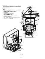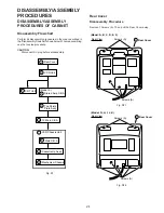
1-12
SUB COLOR
SUB TINT
SUB BRIGHT
CONTRAST
SUB SHARPNESS
R CUT -OFF
G CUT -OFF
B CUT -OFF
G DRIVE
B DRIVE
SUB CONTRAST
H CENTER
V POSITION
V SIZE
DOT CLOCK
ANR CTL
PICTURE CTL
VV COLOR
VV TINT
VV SHARPNESS
PG SHIFTER
C0 – FF, 00 – 3F
E0 – FF, 00 – 1F
C0 – FF, 00 – 3F
C1 – FF, 00
E0 – FF, 00 – 1F
00 – 7F
00 – FF
00 – FF
00 – 7F
00 – 7F
00 – 0F
00 – 0F
00 – 06
00 – 7F
00 – 7F
00 – EF
00 – EF
C0 – FF, 00 – 3F
E0 – FF, 00 – 1F
E0 – FF, 00 – 1F
01 – FD
Control functions
Memory IC Reference Table
Range
Default
00
00
F0
00
F0
1E
3C
3C
40
40
06
08
00
40
34
87
84
00
00
E8
80
Address
00
01
02
03
04
05
06
07
08
09
0A
0B
0C
0D
0E
10
11
12
13
14
15
Note:
Address is not displayed on the TV screen.
Other Addresses except above are not used.
SUB COLOR
SUB COLOR
00
Set
FF
SUB COLOR
FF
Control
Function
Value to be
set
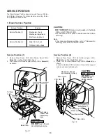
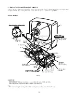
Opener Lever
Cassette Door Tab
View "A"
Cassette Door-Lid
Cassette Door-Lid
VCR Unit
View "A"
Press
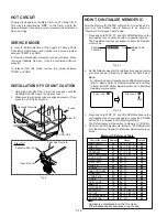
CAUTION
HOT CIRCUIT
Primary circuit exists on the Main C.B.A. and TV Main C.B.A.
This circuit is identified as "HOT" on the C.B.A. and in the
Service Manual. Use extreme care to prevent accidental shock
when servicing.
SERVICE MODE
In order to inhibit detection of the Supply & Takeup Photo
Transistors, Reel Sensor, and Cylinder Lock, place a jumper
between TP6001 and GND.
In this mode, Mechanism movement can be confirmed. When
removing Cassette Up Ass'y, it can be confirmed without a
cassette.
To release from this mode, remove the jumper between
TP6001 and GND.
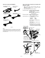
INSTALLATION OF VCR UNIT CAUTION
1. Swing the Cassette Door -Lid all the way open until the
Cassette Door tab clears the Opener Lever.
2. Make sure that all guide tabs are aligned properly. Then,
press the VCR Unit straight in.
Fig. 4
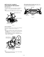
HOW TO INITIALIZE MEMORY IC
After the Memory IC (IC6004) or MainC.B.A. is replaced, be
sure to set the Default value to Memory IC as shown in
"Memory IC Reference Table" below.
1. Press and hold STOP, FF, and VOL DOWN buttons on the
unit together over 5 seconds with no cassette inserted.
The adjustment overlay will appear to Enter EVR Adjust-
ment mode.
Fig. 3-1
2. Set the Default value of all Control functions using a remote
control as shown in "Memory IC Reference Table" below.
Note:
For Selecting Control functions and setting Default value,
refer to "How to Enter EVR Adjustment Mode" and "How
to Enter EVR PG Shifter Adjustment Mode" in Electrical
Adjustment procedures.
Fig. 3-2
3. Press and hold STOP, FF, and VOL DOWN buttons on the
unit together over 5 seconds again or press the POWER
button OFF to release EVR Adjustment Mode.
The Default value will be written to Memory IC (IC6004).
4. Perform all EVR Adjustments. (Refer to "EVR Adjustment
with the Remote Control" in Electrical Adjustment proce-
dures.)
Содержание Omnivision PV-M1378W
Страница 5: ...1 3 ...
Страница 6: ...1 4 ...
Страница 7: ...1 5 ...
Страница 8: ...1 6 ...
Страница 60: ......
Страница 61: ......
Страница 62: ......
Страница 63: ......
Страница 64: ......
Страница 65: ......
Страница 66: ......
Страница 67: ......
Страница 68: ......
Страница 69: ......
Страница 70: ......
Страница 71: ......
Страница 72: ......
Страница 73: ......
Страница 74: ......
Страница 75: ......
Страница 76: ......
Страница 77: ......
Страница 78: ......
Страница 79: ......
Страница 80: ......
Страница 81: ......
Страница 82: ......
Страница 83: ......
Страница 84: ......
Страница 85: ......
Страница 86: ......
Страница 87: ......
Страница 88: ......
Страница 89: ......
Страница 90: ......
Страница 91: ......
Страница 92: ......
Страница 93: ......
Страница 94: ......
Страница 95: ......
Страница 96: ......
Страница 97: ......
Страница 98: ......
Страница 99: ......
Страница 100: ......
Страница 101: ......
Страница 102: ......
Страница 130: ...Printed in Japan ...


