background image

2-10

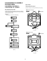
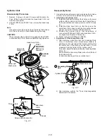
Shaft of Main Cam Gear

Main Cam Gear

Main Cam Push Nut

Bottom of Chassis

Screwdriver

Press

Main Cam 
Gear

Chassis Hole

Chassis Hole

E

E

Drive Rack Arm

Through Hole (A)

Through Holes (B)

Chassis

mark

Main Lever 
Drive Arm

Pin

Through Hole (C)

Pin

7  Main Cam
    Gear

8  Drive Rack
    Arm

Turn

See 
"Reassembly 
 Notes."

Main Cam Push Nut

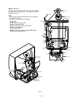
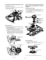
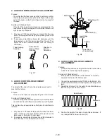
Main Cam Gear and Drive Rack Arm

Disassembly Procedure

1. Remove the Main Cam Push Nut. (Refer to Note.)
2. Pull up on the Main Cam Gear.
3. Turn the Drive Rack Arm fully counterclockwise as shown.
4. Pull up on the Drive Rack Arm.

Fig. J5-1

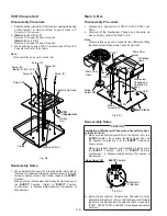
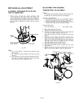
Note:

When removing the Main Cam Push Nut, press the Main
Cam Gear to make space between the Main Cam Push Nut
and Bottom of Chassis. Then, remove the Main Cam Push
Nut using a screwdriver etc.

Fig. J5-2

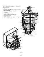
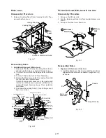
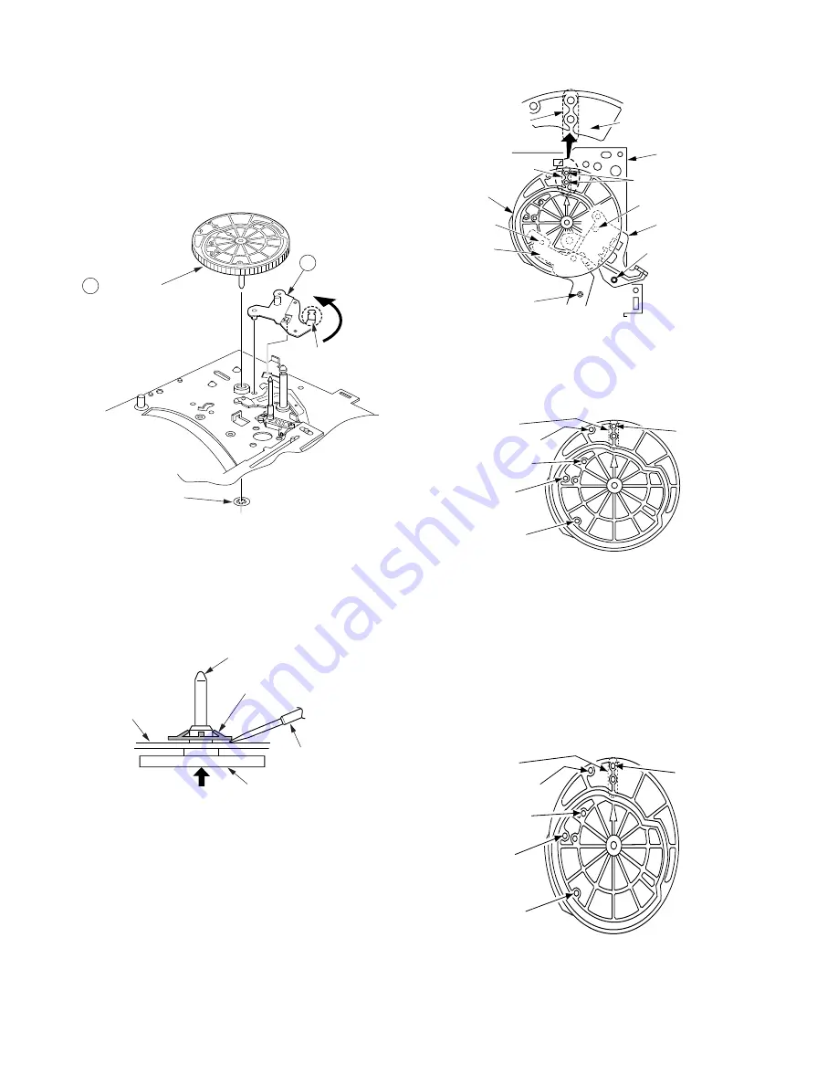
Reassembly Notes

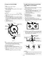
1. Alignment of Main Cam Gear, Drive Rack Arm, and

Main Lever Drive Arm
1) Confirm that the hole (C) on the Main Lever Drive Arm

is aligned with the hole on chassis (Through hole (C)) as
shown.

2) Install the Drive Rack Arm so that the hole (A) is aligned

with the hole on chassis (Through hole (A)) as shown.

3) Install the Main Cam Gear so that the 2 holes (B)

marked "E" are aligned with the hole on chassis (Through
hole (B)) as shown. ("E" indicates the EJECT position.)

Fig. J5-3

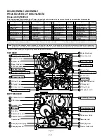
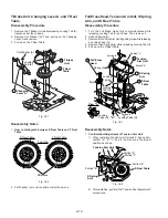
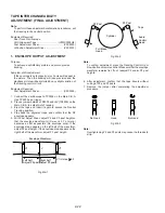
2 . Holes on Main Cam Gear

1) The holes on Main Cam Gear should be aligned with

the hole on chassis in each mode (Through hole) as
shown.

Fig. J5-4

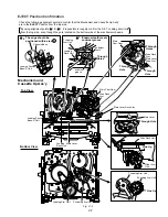
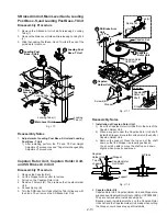
3. Installation of Main Cam Gear and Main Cam Push Nut

1) Position the chassis upside down and place a Support

under the Main Cam Gear.
Install the Main Cam Push Nut with Needlenose Pliers
etc. so that it is flush with the chassis.

There may be some slight scratches on the Shaft of
Main Cam Gear, when removing the Main Cam Gear.
In case that the Main Cam Gear can be installed
securely without tottering, it is fine to use the one. If any
tottering, replace a new one.

Fig. J5-5

4. The Main Cam Push Nut is not reusable. Install a new one.
5. Make sure to hook Spring (A) of the Cassette Up Ass'y to

the Drive Rack Arm. Refer to "Cassette Up Ass'y" in
"Disassembly/Assembly Procedures of Cabinet."

E

FR

R

P

S

EJECT mode
Hole

Chassis Hole

Brake mode Hole

FF/REW mode Hole

REV mode Hole

PLAY/CUE
/SLOW/STILL
mode Hole

E

FR

R

P

S

EJECT mode
Hole

Chassis Hole

Brake mode Hole

FF/REW mode Hole

REV mode Hole

PLAY/CUE
/SLOW/STILL
mode Hole

Содержание Omnivision PV-M1378W

Страница 1: ...PECIFICATION 123456 Head 2 rotary heads helical scanning system 4 rotary heads helical scanning system Input Level VIDEO IN Jack Phono type 1 0 Vp p 75Ω unbalanced Signal to Noise Ratio SP more than 43 dB LP SLP more than 41 dB Horizontal Resolution Color Monochrome more than 230 lines Head Normal Mono 1 stationary head Input Level AUDIO IN Jack Phono type 10 dBv 50kΩ unbalanced Frequency Response...

Страница 2: ... C Process System Control Servo Operation C B A A B E F G H K 4 1 Main Power Supply Signal Process OSD Audio Amp TV Y C Process System Control Servo Operation C B A C D I J 4 5 TV Main C B A 4 9 TV Stereo C B A 4 11 Stereo Amp C B A 4 11 CRT C B A 4 12 Head Amp C B A 4 13 Capstan Stator Unit 4 15 Junction C B A 4 15 Loading Motor P C B 4 16 Audio Control Head P C B 4 16 BLOCK DIAGRAMS Power Supply...

Страница 3: ...ing make the following leakage current checks to prevent the customer from being exposed to shock hazards LEAKAGE CURRENT COLD CHECK 1 Unplug the AC cord and connect a jumper between the two prongs on the plug 2 For physically operated power switches turn power on Otherwise skip step 2 3 Measure the resistance value with an ohmmeter between the jumpered AC plug and each exposed metallic cabinet pa...

Страница 4: ...herwise harmless motion such as the brushing together of your clothes fabric or the lifting of your foot from a carpeted floor can generate static electricity ESD sufficient to damage an ES device NOTE to CATV system installer This reminder is provided to call the CATV system installer s attention to Article 820 40 of the NEC that provides guidelines for proper grounding and in particular specifie...

Страница 5: ...1 3 ...

Страница 6: ...1 4 ...

Страница 7: ...1 5 ...

Страница 8: ...1 6 ...

Страница 9: ... D 0 1 2 3 4 4 Explanation of Codes Code No SERVICE MODE 2192 TV Screen Fault Code Cassette Down SW and S Tab SW Data Take Up Photo and Supply Photo Sensor Data Present mechanism position code Lock code Code Digit Position Power is OFF REW FF Press Over 3 seconds SERVICE NOTES SIMPLIFIED FAULT FINDING DATA SimplifiedSelf DiagnosticSystemfacilitatesfindingthecause of the fault 4 digit fault code wi...

Страница 10: ...ition Purpose SERVICE POSITION The Basic Service Position does not require the use of Exten sion Cables However for more extensive servicing Exten sion Cables should be used 1 Basic Service Position Service Position 1 1 Remove Rear Cover VCR Unit Stereo Amp C B A Model K and Top Shield Plate Ass y 2 Then place VCR Unit and Stereo Amp C B A Model K as shown Fig 2 1 CAUTION HOT CIRCUIT Primary circu...

Страница 11: ... HOT CIRCUIT DO NOT touch Power circuit during service Stereo Amp C B A Model K Insulated material Insulated material 2 Service Position with Extension Cable Kit In Service Position with Extension Cable Kit mechanism check from the Bottom Side of Mechanism Chassis and Capstan Stator Unit Capstan Motor Drive Loading Motor Drive Circuit check with power on condition can be performed Fig 2 3 Service ...

Страница 12: ...TP6023 b 8 Pin Connector P6002 on the Main C B A c 14 Pin Connector P6201 on the Main C B A d Set Mode Select SW on the Mode Select SW Ass y to EJECT position and install onto Mechanism Chassis Extension Cable 2 VUVS0005 for 2 Head Model Mode Select SW Ass y VUVS0001 8 pin 3 clip on wires 14 pin 2 pin 12 pin 15 pin 20 pin Extension Cable 2 VUVS0004 for 4 Head Model Extension Cable 2 VUVS0003 for H...

Страница 13: ...turn this SW on Note To avoid damaging the connectors on Main C B A it is necessary to secure connectors with tape as shown 5 Set Mode Select SW on the Main C B A to Service Position 6 Plug the AC plug into an AC outlet 7 Insert a cassette The power comes on the tape is fully loaded and the unit goes into the STOP Mode 8 Place a jumper between TP6001 and GND to place the unit in Service Mode 9 Che...

Страница 14: ... and GND In this mode Mechanism movement can be confirmed When removing Cassette Up Ass y it can be confirmed without a cassette To release from this mode remove the jumper between TP6001 and GND INSTALLATION OF VCR UNIT CAUTION 1 Swing the Cassette Door Lid all the way open until the Cassette Door tab clears the Opener Lever 2 Make sure that all guide tabs are aligned properly Then press the VCR ...

Страница 15: ...med or locked Fig 5 1 Electrical Method Remove the solder as shown and apply 10 0 VDC Power Supply DC to Portion a DC to Portion c Note Be careful not to let the DC Power Supply Unit GND contact the chassis GND This may damage the Loading Motor Drive IC IC 2501 Be sure to apply DC to Portion a of Motor P C B If DC is applied to Portion b the Loading Motor Drive IC IC2501 may be damaged Fig 5 2 Not...

Страница 16: ...Capstan Rotor Unit Fig 6 2 3 Remove the tape from the tape path 4 Rewind the tape into the cassette by rotating the Center Clutch Unit counterclockwise 5 Unhook Spring A of the Drive Rack Unit 6 Remove Screw A 7 Lift the Drive Rack Unit up so that the slot clears the guide tab WhilepullingtheDriveRackUnitoutfarenoughsothat it clears the Drive Rack Arm slide the Drive Rack Unit as indicatedbythearr...

Страница 17: ...ying 10 0VDC Power Supply again 5 After completing the removal procedure resolder Jumper J6004 Electrical Method Electrical method can only be performed when the mechanism is moved by rotating the Main Cam Gear CAUTION If loading does not start in approx 2 seconds after DC Power Supply is applied DO NOT continue to apply DC Power Supply Instead perform Manual Method Method 1 1 Remove the solder as...

Страница 18: ... Leads C805 Power circuit on Main C B A Model A B C D E F After servicing make sure that all wires leads and clampers are placed in their original position It is important for the best operation of the unit Note No lead wires or flat cables should touch any heating parts or the Heat Sink Plate Use extreme care especially for followings Anode Lead DO NOT touch the Picture Tube Speaker Connector Lea...

Страница 19: ...t on Main C B A P1002 Connector Leads DO NOT touch C805 Deflection Yoke Connector Leads and CRT Leads DO NOT touch Heat Sink Plate CRT Leads Anode Lead Picture Tube Hea t Sink Plate Deflection Yoke Connector Leads P1002 Connector Leads Speaker Connector Leads C805 Model G H I J After servicing make sure that all wires leads and clampers are placed in their original position It is important for the...

Страница 20: ...Sink Plate Deflection Yoke Connector Leads P1002 Connector Leads Speaker Connector Leads C805 After servicing make sure that all wires leads and clampers are placed in their original position It is important for the best operation of the unit Note No lead wires or flat cables should touch any heating parts or the Heat Sink Plate Use extreme care especially for followings Anode Lead DO NOT touch th...

Страница 21: ... personal injury from electrical shocks It will also protect Combination VCR from being damaged by accidental shorting that may occur during servicing Also when troubleshooting the above type of Power Supply Circuit a variable isolation transformer is required in order to increase the input voltage slowly SPECIAL NOTE All integrated circuits and many other semiconductor devices are electrostatical...

Страница 22: ...es of Schematic Diagram and Circuit Board Layout Notes for mark Z Tweezers Solder Soldering Iron b Press the part downward with tweezers and solder both electrodes as shown below Fig 9 3 Note Do not glue the replacement leadless component to the circuit board MODEL NO IDENTIFICATION MARK Use Marks shown in the chart below to distinguish the different models included in this Service Manual ...

Страница 23: ...value using the schematic diagram CAUTION Once chip parts are removed they must not be reused Always use a new part when installing a chip part 1st 2nd 3rd B E C CRT C B A LA7837 2SD2586LBK 2SD2499LBK STR30130 2SC3063 2SD601 2SD601A 2SB709 2SB709A TV MAIN C B A E C B E B C 2SC3852 2SC4533LP KT 2SC5130LF608 1 2 4 3 E C B AN5265 AN3809K ON3131 R KT ON3131 S KT 2SC945A 2SA733 2SC1994 2SC1473 QNC AN53...

Страница 24: ...ES OF CABINET Disassembly Flowchart Perform all disassembly procedures in the order described in the DisassemblyFlowchart shownbelow Whenreassembling use the reverse procedure CAUTION Disconnect AC plug before disassembly Fig D1 Rear View Screws A Screws A 1 Rear Cover Model G H I J K Rear View Model A B C D E F Screws A Screws A 1 Rear Cover Rear Cover Disassembly Procedure Remove 7 Screws A Then...

Страница 25: ...s P4604 and P4605 on the Stereo Amp C B A and remove the leads from the clampers Fig D3 1 6 Model A B C D E F Slightly lift up the rear side of the VCR Unit to release 2 Tabs B Model G H I J K Slightly lift up the rear side of the VCR Unit to release 4 Tabs B and C 7 Slide the VCR Unit out as far as it will go Then lift up the VCR Unit to release 3 Guide Tabs A and remove the VCR Unit all the way ...

Страница 26: ...B A Then remove the Stereo Amp C B A Fig D5 PK2 PK1 PK3 Frame P1002 Main C B A Locking Tabs B A C Cord 6 TV Main C B A Screw B Screw B Clampers B Clamper Clamper 5 Top Shield Plate Ass y Screw with Washer B Top Shield Plate Ass y Disassembly Procedure 1 Remove 2 Screws B and Screw with Washer B 2 Release the 2 Clampers B on the Top Shield Plate Ass y and remove the leads from the clampers Then Rem...

Страница 27: ... SERVICE Rotate P3501 P2531 P2552 Mode Select SW Mode Select SW Sensor LED 8 Main C B A P4001 Mechanism Chassis and Cassette Up Ass y Full Erase Head Hole Shaft Main Cam Gear Main Cam Gear Main C B A Disassembly Procedure 1 Disconnect 4 Connectors of P2531 P2552 P3501 and P4001 2 Carefully lift the Mechanism Chassis and Cassette Up Ass y straight out from the Main C B A Note Work carefully so as n...

Страница 28: ...cking Tab D Then lift it up and remove Fig D10 Reassembly Notes Installation of Cassette Up Ass y 1 Confirm that the 3 pins and Locking Tab D under the Cassette Up Ass y are in each of the 4 Guide Holes on the MechanismChassiswheninstallingtheCassetteUpAss y Then slide the Cassette Up Ass y towards the back 2 Slide Holder Unit refer to Method for Loading Unload ing of Mechanism in Service Notes to...

Страница 29: ...5 Arm Unit Part Prior Step s Step Loc No Part Prior Step s Step Loc No Part Prior Step s Step Loc No Part Prior Step s Step Loc No 1 2 3 4 5 6 7 8 9 10 Main Lever Drive Arm 3 4 5 7 8 9 9 9 9 12 13 16 17 9 16 17 18 9 T Brake Unit Changing Lever A T Reel Table Full Erase Head Tension Arm Unit S Spring Arm S Reel Table S Brake Arm Unit Main Lever Guide 11 12 13 14 15 16 17 18 19 20 Loading Post Base ...

Страница 30: ...Main Lever Through Hole Line Up T Loading Arm Unit S Loading Arm Unit Main Cam Gear Drive Rack Arm Through Holes Through Hole Through Hole Main Lever Drive Arm Loading Rack Unit T Loading Arm Unit endmost groove endmost tooth Endmost tooth meets endmost groove Through Holes 1 Loading Post Base S Unit 2 Chassis Boss Edge The edge should be positioned within area A A Bottom View Loading Rack Unit Lo...

Страница 31: ...stallation of Cylinder Unit 1 Install the Cylinder Unit so that the 2 holes on the lower surface of the Cylinder Unit fit over the 2 Guide Pins on the Cylinder Base and loosely secure it with 3 Screws A 2 Install the Head Amp C B A so that the hole on the Head Amp C B A lines up with the hole on the chassis and secure it with 2 Screws with Washers A 3 Position the Cylinder Unit so that foil patter...

Страница 32: ... 2 Alignment of Upper Cylinder Unit 1 When installing make sure that the hole on the Upper Cylinder is aligned with the indentation on the Lower Cylinder 2 After installing perform the Tape Interchangeability Adjustment procedures Opener Piece Pinch Arm Unit Motor Block Ass y AudioControlHeadUnit andCleaner Arm Unit Disassembly Procedure 1 Remove the Opener Piece by pulling it upward while releasi...

Страница 33: ...hrough hole A as shown 3 Install the Main Cam Gear so that the 2 holes B marked E arealignedwiththeholeonchassis Through hole B as shown E indicates the EJECT position Fig J5 3 2 Holes on Main Cam Gear 1 The holes on Main Cam Gear should be aligned with the hole on chassis in each mode Through hole as shown Fig J5 4 3 Installation of Main Cam Gear and Main Cam Push Nut 1 Position the chassis upsid...

Страница 34: ...holes 2 Turn the P5 Arm Unit to the Capstan Rotor Unit Shaft side 3 Turn the T Brake Unit to the T Reel Table side 4 Position the Main Lever so that the Loading Rack Unit Pin fits in the niche of Main Lever Confirm that pins and bosses are in the position and that the hole of Main Lever is aligned with the hole on chassis Through hole as shown Then install the Main Lever 5 Push down the Locking Ta...

Страница 35: ... distinguish between S Reel Table and T Reel Table Fig J8 2 2 Cut Washer A is not reusable Install a new one FullEraseHead TensionArmUnit SSpring Arm and S Reel Table Disassembly Procedure 1 Turn the Full Erase Head fully counterclockwise while releasing Locking Tab F as shown Then remove it 2 Unhook Spring A 3 RemovetheTensionArmUnitbypullingitupwhilereleasing 2 Locking Tabs G 4 Remove the S Spri...

Страница 36: ...or Unit Capstan Holder Unit and SS Brake Arm Unit Disassembly Procedure 1 Remove the Capstan Belt 2 Cut the Stopper with a cutter to remove 3 Pull up on the Capstan Rotor Unit 4 Remove 3 Screws B Then remove the Capstan Holder Unit 5 Unhook Spring B 6 Turn the SS Brake Arm Unit so that the Tab A lines up with the niche Then remove the SS Brake Arm Unit Fig J11 1 Reassembly Notes 1 Installation of ...

Страница 37: ...y as a replacement part Capstan Rotor Unit Capstan Holder Unit and Stopper are not reusable Install all new parts BecauseeveninvisiblescratchesontheCapstanRotor Unit shaft and the Capstan Holder Unit made when cutting the Stopper could cause tape path instability 3 Adjustment of FG Head 1 After installing perform the FG Head gap Adjustment procedures 29 PCB Holder 27 Capstan Stator Unit IC2501 CAU...

Страница 38: ... Notes 1 Installation of Center Clutch Unit 1 Fit the Center Clutch Unit into the Changing Gear as shown Fig J14 2 2 Cut Washer B is not reusable Install a new one Center Clutch Unit Changing Gear T Loading Arm Unit and S Loading Arm Unit Disassembly Procedure 1 Remove the T Loading Arm Unit by pulling it up while releasing Locking Tab K 2 Pull up on the S Loading Arm Unit Fig J13 1 Reassembly Not...

Страница 39: ...move Top Plate by releasing 2 Locking Tabs A on the left side and 2 Locking Tabs B on the right side of the Top Plate 2 Remove Wiper Arm Unit by releasing 2 Locking Tabs C Then remove the Holder Unit Fig K1 1 Loading Rack Unit Disassembly Procedure 1 Slide the Loading Rack Unit as indicated by the arrow Then pull up on the Loading Rack Unit Fig J15 Reassembly Notes 1 Alignment of Loading Rack Unit...

Страница 40: ...ar right as indicated by the arrow 2 Install the Wiper Arm Unit so that the hole on the Wiper Arm Unit is aligned with the hole on the Drive Rack Unit Fig K1 2 2 Installation of Holder Unit 1 Turn the Wiper Arm Unit so that the grooves on each end are aligned with the each groove on Side Plate L and R 2 Insert Holder Unit boss A and B into the grooves See Fig K1 1 on previous page 3 Finally in the...

Страница 41: ...on Cable Kit VFK27 Head Cleaning Stick VFK0330 H Position Adjustment Driver VFKS0081 Grease Video Audio Color Bar Monoscope 6kHz MONO Extension Cable 2 VUVS0005 for 2 Head Model Mode Select SW Ass y VUVS0001 Extension Cable 2 VUVS0004 for 4 Head Model Extension Cable 2 VUVS0003 for Hi Fi Model Extension Cable 1 VUVS0002 8 pin 3 clip on wires 14 pin TSM10032 2 Model G H I J K Permalloy Magnetic Str...

Страница 42: ...ench adjust the nut on the Tension Adjust Piece counterclockwise only so that there is a space of 1 mm between the left edge of the P1 Post and the right edge of the Tension Post Make sure that the center of the Hex Wrench hole is within Area A 5 After adjustment remove the Hex Wrench 6 Press the STOP EJECT button to place the unit in the EJECT Mode 7 Release the unit from the Service Mode Refer t...

Страница 43: ...ion 25 2 5g 1 Play back a T120 cassette tape from the beginning for approx 10 to 20 seconds to stabilize tape movement 2 InsertaTensionMeterintotapepathandmeasuretheback tension 3 If the reading is out of specification make sure that there is no dust or foreign material between the Tension Band of Tension Arm Unit and the Reel Table If cleaning does not correct the tension measurement replace the ...

Страница 44: ...han 15mVp p P2 AND P3 POST HEIGHT ADJUSTMENT PRELIMINARY ADJUSTMENT Purpose To properly align the position of the tape with the Cylinder Lead so that the tape runs with stability Symptom of Misadjustment 1 Since the Envelope Waveform Signal cannot be tracked properly the Playback picture will be poor 2 Since the tape does not run smoothly the tape will eventually be damaged 3 Tape interchangeabili...

Страница 45: ... the tape and insert it again to access the Neutral Tracking position 4 Play back the alignment tape and confirm that the RF envelope appears 5 With Post Adjust Driver adjust P2 and P3 post height so that the envelope waveform V1 V max is 0 7 or more becomes as flat as possible No envelope drop If the envelope drop appears on the left half of the waveform adjust P2 post height If the envelope drop...

Страница 46: ...l Head Symptom of Misadjustment Ifthecontrolsignalisnotproperlypickedup Servo Operation cannot be achieved A Blue screen will be seen in Playback This confirmation is required when the Audio Control Head is replaced 1 Play back a T120 cassette tape and check that the lower edge of the tape runs approximately 0 25 mm above the lower edge of the Audio Control Head 2 If necessary adjust Black Screws ...

Страница 47: ...velope is at maximum 6 Before finding the center of the maximum period of the envelope rotatethefixturebackandforthslightlytoconfirm the limits on either side of the maximum period 7 Push the Tracking Control Up Button on the Remote Control several times count the number of times pushed until the maximum envelope is reduced to 1 2 8 Reset the tracking to the neutral position by ejecting the tape a...

Страница 48: ...l INPUT Antenna Input Terminal MTS ONLY L CH 300Hz 5Hz 14 or 7 Modulating Mode STEREO audio TV Equipment Oscilloscope MTS SAP Signal Generator 1 Connect the RF OUTPUT of the MTS SAP Signal Generator to the Antenna Input Terminal 2 Connect the Oscilloscope to TP4202 R CH on the TV Stereo C B A 3 Set to TV mode and then set to STEREO audio 4 Adjust R4901 on the TV Stereo C B A so that the signal lev...

Страница 49: ...is unit has electronic technology using I2 C Bus concept The following control functions are adjusted by using On Screen Displays and the remote control instead of adjusting mechanical controls VR Note 1 After SUB COLOR SUB TINT ADJUSTMENT is complete perform as follows Write the same value of SUB COLOR Address 00 to VV COLOR Address 12 Write the same value of SUB TINT Address 01 to VV TINT Addres...

Страница 50: ...justment if necessary Fig E4 5 How to release from EVR Adjustment Mode Press and hold STOP FF and VOL DOWN buttons on the unit together over 5 seconds again or press the POWER button OFF The adjusted value will be written to Memory IC IC6004 HOW TO ENTER EVR PG SHIFTER ADJUSTMENT MODE 1 Enter EVR adjustment mode 2 Insert the VHS Alignment Tape and playback in SP mode The adjustment overlay will ap...

Страница 51: ...e of the head switching pulse is placed 6H 1H 0 38 0 06msec before the start of the vertical sync pulse 4 Release EVR PG Shifter Adjustment Mode The adjusted value will be written to Memory IC IC6004 Fig E5 OSD CLOCK FREE RUN FREQUENCY ADJUSTMENT Purpose To set the OSD clock free run frequency Symptom of Misadjustment May make it so that on screen and closed caption display do not appear Test Poin...

Страница 52: ...ode so that the level A is 140 5VDC Model A B C D E F or 170 5VDC Model G H I J K Fig E7 8 Turn the SCREEN CONTROL on the Flyback Transformer clockwise carefully and stop at the point where any color is first observed 9 InEVRadjustmentmode selectthetwocolorsnotobserved in step 8 from the following control functions B CUT OFF G CUT OFF or R CUT OFF and adjust so that the horizontal line becomes whi...

Страница 53: ... Select SUB BRIGHT in EVR adjustment mode Then after making a note of the original value adjust to the minimum C0 3 Connect the Oscilloscope to Pin 5 of P6001 on the Main C B A or TP49 on the CRT C B A 4 Select SUB TINT in EVR adjustment mode and adjust so that level A and B should be equal in amplitude Fig E8 1 10 Press DISPLAY key on the remote control again to return for full frame scan 11 Sele...

Страница 54: ...eo Input Jack 5 Turn the pair of 4 Pole Convergence Magnet Rings so that B and R at the center of CRT overlap each other 6 Turn the pair of 6 Pole Convergence Magnet Rings so that B and R which overlapped each other in Step 5 overlap G 7 Supply a White Pattern Signal to Video Input Jack 8 Select G CUT OFF in EVR adjustment mode and adjust it to become to the minimum level Turn the Pair of Purity M...

Страница 55: ...VERGENCE ADJUSTMENT Purpose To set the uniform convergence over the whole screen Symptom of Misadjustment The convergence on the screen will vary from the center portion to the surrounding edges Test Point Adjustments Pair of 4 Pole Convergence Magnet Rings Pair of 6 Pole Convergence Magnet Rings Specification Refer to descriptions below Input Video Input Jack Crosshatch Pattern Signal Mode STOP E...

Страница 56: ...t mode and adjust so that the top 3rd line is just in view 3 Confirm that the 10th dotted line is in view and that the 11th line is out of view If the lines are not positioned correctly readjust V SIZE so that the top 3rd line is within 2mm from the top edge of the screen Confirm that the 10th dotted line is in view and that the 11th line is out of view 4 Select H CENTER in EVR adjustment mode and...

Страница 57: ...ack Transformer so that the center of picture is the sharpest 5 Press DISPLAY key Service Switch on the remote control for collapse scan Refer to How to Enter Service Mode 6 Turn the SCREEN CONTROL on Flyback Transformer fully counterclockwise 7 Adjust SUB BRIGHT in EVR adjustment mode so that the level A is 140 5VDC Model A B C D E F or 170 5VDC Model G H I J K Fig E12 8 Turn the SCREEN CONTROL o...

Страница 58: ...eo Signal to Jack REC PB Video envelope signal Normal Audio signal Service Test Point inhibit sensors defeat Auto tracking function connect to 5V TP6009 PG Shifter Adjustment Mode connect to GND 5V Head SW Mode Select SW Position Mode Position A Mode Position B Mode Position C GAME POWER POWER FM TV Model A B C D E F Model A B C D E F Model G H I J K Model A B C D E F Model A B C D E F Model G H I...

Страница 59: ...50 TP47E TP49 Foil Side TV Main C B A Component Side PK2 TV Stereo C B A Model K Foil Side TV STEREO SECTION FM MPX SECTION TP4202 TP9201 P4201 P4204 8 22 29 25 4 21 4 pin 25 pin 2 pin FM VCO R4901 R9206 SEPARATION ADJ ...

Страница 60: ......

Страница 61: ......

Страница 62: ......

Страница 63: ......

Страница 64: ......

Страница 65: ......

Страница 66: ......

Страница 67: ......

Страница 68: ......

Страница 69: ......

Страница 70: ......

Страница 71: ......

Страница 72: ......

Страница 73: ......

Страница 74: ......

Страница 75: ......

Страница 76: ......

Страница 77: ......

Страница 78: ......

Страница 79: ......

Страница 80: ......

Страница 81: ......

Страница 82: ......

Страница 83: ......

Страница 84: ......

Страница 85: ......

Страница 86: ......

Страница 87: ......

Страница 88: ......

Страница 89: ......

Страница 90: ......

Страница 91: ......

Страница 92: ......

Страница 93: ......

Страница 94: ......

Страница 95: ......

Страница 96: ......

Страница 97: ......

Страница 98: ......

Страница 99: ......

Страница 100: ......

Страница 101: ......

Страница 102: ......

Страница 103: ... the unit Note Parts with no Ref No in EXPLODED VIEW are not supplied And some Ref No will be skipped Be sure to make your orders of replacement parts according to the parts list Mark Kind of Lubricant Availability Part Number Silicon Grease Available from Factory VFK1301 Spindle Oil Purchase from Local Supplier Grease Available from Factory VFKS0081 431 31 32 33 A A G COMPARISON CHART OF MODELS M...

Страница 104: ...or Unit Capstan Holder Unit and Stopper are supplied as a Capstan Rotor Kit only 2 Capstan Stator Unit Capstan Rotor Unit Capstan Holder Unit and Stopper are supplied as a Capstan Stator Kit only However IC2501 AN3845SC is available separately as a replacement part 3 When installing the IC2501 or Capstan Stator Unit be sure to apply Silicon Grease VFK1301 Refer to Capstan Stator Unit of Disassembl...

Страница 105: ...ant Availability Part Number Silicon Grease Available from Factory VFK1301 Spindle Oil Purchase from Local Supplier Grease Available from Factory VFKS0081 CASSETTE UP COMPARTMENT SECTION 69 4 As an ESD Countermeasure the spring should be installed in the proper position Please refer to Disassembly Assembly Procedure of Mechanical Section for more information 62 64 67 70 61 68 66 65 63 4 ...

Страница 106: ... USE ONLY THE SPECIFIED PARTS IMPORTANT SAFETY NOTICE COMPONENTS IDENTIFIED BY THE SIGN HAVE SPECIAL CHARACTERISTICS IMPORTANT FOR SAFETY WHEN REPLACING ANY OF THESE COMPONENTS USE ONLY THE SPECIFIED PARTS To A in Chassis Frame Section 2 A To B in Chassis Frame Section 2 B 95 94 94 90 119 445 445 443 445 445 169 119 443 92 48 93 71 83 92 93 84 82 81 72 38 K A B E F G H K A B C D E F I J G H I J K ...

Страница 107: ...NENTS IDENTIFIED BY THE SIGN HAVE SPECIAL CHARACTERISTICS IMPORTANT FOR SAFETY WHEN REPLACING ANY OF THESE COMPONENTS USE ONLY THE SPECIFIED PARTS IMPORTANT SAFETY NOTICE COMPONENTS IDENTIFIED BY THE SIGN HAVE SPECIAL CHARACTERISTICS IMPORTANT FOR SAFETY WHEN REPLACING ANY OF THESE COMPONENTS USE ONLY THE SPECIFIED PARTS To A in Chassis Frame Section 1 A 97 E2 404 460 449 449 449 460 404 404 460 T...

Страница 108: ...F G H 1 2 3 4 5 6 6 PACKING PARTS AND ACCESSORIES SECTION A B C D E F 6 The Infrared Remote Control Unit replacement part is available as a complete assembly unit only Do not try to disassemble the Infrared Remote Control Unit However the battery cover is available separately as a replacement part not supplied 123 100 126 125 56 118 132 135 136 131 121 6 122 122 A B C D E F ...

Страница 109: ... B C D E F G H 1 2 3 4 5 6 6 118 132 131 121 122 PACKING PARTS AND ACCESSORIES SECTION G H I J K 6 The Infrared Remote Control Unit replacement part is available as a complete assembly unit only Do not try to disassemble the Infrared Remote Control Unit However the battery cover is available separately as a replacement part not supplied 123 100 127 128 130 129 56 6 ...

Страница 110: ...LATOR UNIT replacement part is available as a complete assembly unit only 5 The Infrared Remote Control Unit Ref No 123 replace ment part is available as a complete assembly unit only Do not try to disassemble the Infrared Remote Control Unit However the battery cover is available separately as a replacement part 6 Cut Washers Ref No 416 and 417 are not reusable If removed install a new one 7 Main...

Страница 111: ...Ic F Q hbf UN mltbo _rqqlk i_uSNMOP E Ib F Q hbf i_uSNMPN E _Ic F Q hbf i_uSNMMV E F Q hbf i_uSNMOT E a F Q hbf i_uSNMMN E dIeIh F Q hbf i_uSNMMR E f F Q hbf i_uSNMNT E g F Q hbf UO e sli _rqqlk i_uSNMOR E Ib F Q hbf i_uSNMPP E _Ic F Q hbf i_uSNMNM E F Q hbf i_uSNMOU E a F Q hbf i_uSNMMP E dIeIh F Q hbf i_uSNMMS E f F Q hbf i_uSNMNU E g F Q hbf MECHANICAL REPLACEMENT PARTS LIST The complete Explod...

Страница 112: ...k ofdeqIpqvolcl j imgSNMMR E I_I IaIbIc F S hbf NOS qlm rpeflk ibcqIpqvolcl j imgSNMMS E I_I IaIbIc F S hbf NOT qlm rpeflk colkqJiIpqvolcl j imgSNMOP E dIeIfIgIh F S hbf NOU qlm rpeflk colkqJoIpqvolcl j imgSNMOQ E dIeIfIgIh F S hbf NOV qlm rpeflk ob oJiIpqvolcl j imgSNMOR E dIeIfIgIh F S hbf NPM qlm rpeflk ob oJoIpqvolcl j imgSNMOS E dIeIfIgIh F S hbf NPN _lqqlj rpeflk colkqIpqvolcl j imgSOMMR E I...

Страница 113: ...pKaK hbf f QNRN kROSR f I ifkb o rafl jm E I_IbIcIdIe F f RPMN kRPSTc_ f I ifkb o vL pfdk i mol bpp hbf f SMMN aTUQVOTvdNMN f I NS_fq jf olmol bpplo bKpKaK hbf f SMMO k NUMNk obbi pbkplo rkfq f SMMP k NUMNk obbi pbkplo rkfq f SMMQ OQi MN_LmpN f I Nh bbm olj jbjlov bKpKaK TRANSISTORS nNMMN Op QRPPimKhq lo Op RNPMicSMU nNMMO OpaNQRU nNMMP OpaSPSEnIoIpF nNMMQ Op_SQNEnIoIpF nNMMR Op_SQNEoIpF nNMRN Op ...

Страница 114: ...MQP bogSdbvgOOOs jdc efm NLNMt OKOh E I_IdIe F oPMQQ bogSdbvgRSOs jdc efm NLNMt RKSh E I_IdIe F oPMQR boapOqgNUO NKUh E I_IdIe F oPMQS bogSdbvgRSOs jdc efm NLNMt RKSh E I_IdIe F oPMTT bogSdbvgNMNs jdc efm NLNMt NMM oPMUN bogSdbvgNMPs jdc efm NLNMt NMh oPMUO bogSdbvgOOPs jdc efm NLNMt OOh oPMUP bogSdbvgOTNs jdc efm NLNMt OTM oPMUQ bogSdbvgOOOs jdc efm NLNMt OKOh oPMUR bogSdbvgNUNs jdc efm NLNMt NUM...

Страница 115: ...NMt NMM oRRMN bogSdbvgOTNs jdc efm NLNMt OTM oRRMO bogSdbvgPVQs jdc efm NLNMt PVMh oRRMP boapOqgQTN QTM oRRMQ bogSdbvgNMNs jdc efm NLNMt NMM oRRMR bogSbkcPOQNs jdc efm HJNB NLNMt PKOQh hbf oRRMU bogSdbvgRSNs jdc efm NLNMt RSM oRRNM bogSdbvgNMNs jdc efm NLNMt NMM oRRNN bogSdbvgOOOs jdc efm NLNMt OKOh oRRNO bogSdbvgNRNs jdc efm NLNMt NRM oRRNP bogSdbvgNMNs jdc efm NLNMt NMM oRSMN boapOqgRSO RKSh oRS...

Страница 116: ...B NORs PPMMm lo b hjopPPOjbv bo jf HJOMB NORs PPMMm hbf lo s hpbhaPPOjv bo jf HJOMB NORs PPMMm lo s hpbsaPPOjv bo jf HJOMB NORs PPMMm lo s hpqhdPPOju bo jf HJOMB NORs PPMMm lo s hpqjdPPOju bo jf HJOMB NORs PPMMm lo s hprhaPPOju bo jf HJOMB NORs PPMMm lo s hprjaPPOju bo jf HJOMB NORs PPMMm NMMP s hpchhNMOju bo jf HJOMB NORs NMMMm lo s hpcjhNMOju bo jf HJOMB NORs NMMMm hbf lo s hpcshNMOju bo jf HJOM...

Страница 117: ... F QNRQ b b Nbh QoT bib qolivqf ORs QKT E I_IbIcIdIe F QNRR b b Nbh QoT bib qolivqf ORs QKT E I_IbIcIdIe F QNRS b NbjQTN_ bib qolivqf ORs QTM E I_IbIcIdIe F QNRU b rsNbQTPwck efm HUMBJOMB ORs MKMQT E I_IbIcIdIe F QNRV b b N h NMM bib qolivqf NSs NM E I_IbIcIdIe F QNSM b N jNMN_ bib qolivqf NSs NMM E I_IbIcIdIe F QNSN b rsNbQTPh_k efm ORs MKMQT E I_IbIcIdIe F QNSP b rsNeNMPwck efm HUMBJOMB RMs MKMN...

Страница 118: ...ONQMRo mrpe ptfq e ptSPNM bsnm_MMRh mrpe ptfq e hbf ptSPNN bsnONQMRo mrpe ptfq e E I_IbIc F ptSPNO bsnm_MMRh mrpe ptfq e hbf ptSPNP bsnm_MMRh mrpe ptfq e hbf E dIeIh F ptSPNQ bsnONQMRo mrpe ptfq e E dIeIh F ptSPNR bsnm_MMRh mrpe ptfq e hbf E dIeIh F FUSE PROTECTOR cNMMN spcpMMMP NS crpb NORs NKS lo spcpMMNO NS crpb NORs NKS lo spcpMMOU NS crpb NORs NKS lo u_ N NSkrNMM crpb NORs NKS moNMMN f mJcPUJ...

Страница 119: ...NMNQ boapOqgOON OOM oNMNR boapOqgOON OOM oNMNS boapOqgRSO RKSh oNMNT boapOqgNMP NMh oNMNU boapOqgNUP NUh oNMNV boapOqgPVO PKVh oNMOM boapOqgSUO SKUh oNMOO boapOqgOON OOM oNMRN bogSdbvgQTOs jdc efm NLNMt QKTh oNMRO boapOqgNRP NRh oNMRP boapOqgNRP NRh oNMRT boapOqgNUO NKUh oPMMN boapOqgOON OOM oPMMQ bogSdbvgNMPs jdc efm NLNMt NMh oPMMR bogSdbvgNMOs jdc efm NLNMt Nh oPMMS boapOqgOON OOM oPMNM bogSdbv...

Страница 120: ...jdc efm NLNMt OKTh oRPOM bogSdbvgOOPs jdc efm NLNMt OOh oRPON bogSdbvgOOPs jdc efm NLNMt OOh oRPOO bogSdbvgNMOs jdc efm NLNMt Nh oRPOP bogSdbvgSUOs jdc efm NLNMt SKUh oRQMN bogSdbvgRSNs jdc efm NLNMt RSM oRQMO bogSdbvgPVQs jdc efm NLNMt PVMh oRQMP bogSdbvgOONs jdc efm NLNMt OOM oRQMR bogSdbvgUOOs jdc efm NLNMt UKOh oRQMS bogSdbvgNMNs jdc efm NLNMt NMM oRRMN bogSdbvgOTNs jdc efm NLNMt OTM oRRMO bog...

Страница 121: ...MNN b b NerQoT bib qolivqf RMs QKT NMNO b b NmbbPPN bib qolivqf NUs PPM NMNP b b NmbbPPN bib qolivqf NUs PPM NMNQ b b NedbQTM bib qolivqf RMs QT NMNS b b NmbbPPN bib qolivqf NUs PPM NMNT b b NmbbPPN bib qolivqf NUs PPM NMNU b n_NeNMQmV mlivbpqbo HNMMBJMB RMs MKN NMON b b NehdMNM bib qolivqf RMs N NMOR b haopOONj_ bo jf HJOMB NORs OOMm lo b hjopOONj_v bo jf HJOMB NORs OOMm hbf lo s hpbgaOONht bo jf...

Страница 122: ...QTM bib qolivqf NSs QT RRMS b rsNeNMPwck efm HUMBJOMB RMs MKMN RRMT b b N h NMM bib qolivqf NSs NM RRMU b rsNeOONgpk efm HJRB RMs OOMm hbf RRNM b b Neh MNM bib qolivqf RMs N RRNN b rsNbPPPh_k efm ORs MKMPP RRNS b rsNbPPPh_k efm ORs MKMPP RSMN b rsNeNMPwck efm HUMBJOMB RMs MKMN RSMO b rsNbNMQh_k efm ORs MKN RSMP b rsNeNRMg k efm HJRB RMs NRm RSMQ b b Neh MNM bib qolivqf RMs N RSMR b rsNeNRPh_k efm ...

Страница 123: ... cj pfdk i mol bpp hbf f VPMN q QMRO_m f I jlp pq ka oa ildf bKpKaK hbf ptfq efkd f VPMO rm QRTM f I ifkb o lm jm TRANSISTORS nQPMN Op TPPEqmF hbf nVPMN Op VQR EqmF hbf nVPMO Op VQR EqmF hbf DIODES aQPMN j NSR aQPMO j NSR aQPMP j NSR aQPMQ j NSR aVPMN j NSR RESISTORS oQPMN bogSdbvgNMNs jdc efm NLNMt NMM oQPMO bogSdbvgNMNs jdc efm NLNMt NMM oQPMP bogSdbvgNUOs jdc efm NLNMt NKUh oQPMQ bogSdbvgNOQs j...

Страница 124: ... rsNbNMQwck efm HUMBJOMB ORs MKN PRMU b rsNbNMQwck efm HUMBJOMB ORs MKN PRNN b rsNbNMQwck efm HUMBJOMB ORs MKN PRNO b rsNbNMQwck efm HUMBJOMB ORs MKN PRNP b rsNbNMQwck efm HUMBJOMB ORs MKN PROU b rsNbNMQwck efm HUMBJOMB ORs MKN PROV b rsNeNMPwck efm HUMBJOMB RMs MKMN COILS iPRMN bibpkNMNh NMM PIN HEADERS mPRMN sgppMUUP lkkb qlo NOm HEAD AMP C B A E F K INTEGRATED CIRCUITS f OSMN kPUMVh f I ifkb o ...

Страница 125: ...QSMT s vp_obNMPhu bo jf ORs MKMN hbf QSMU b N jNMM_ bib qolivqf NSs NM QSMV b N jNMN_ bib qolivqf NSs NMM QSNM s vp_obQTPhu bo jf ORs MKMQT hbf QSNN b N jQTM_ bib qolivqf NSs QT QSNO b N jNMM_ bib qolivqf NSs NM QSNP b NejQoT_ bib qolivqf RMs QKT QSNQ s vp_obNMPhu bo jf ORs MKMN hbf QSNR b N jNMM_ bib qolivqf NSs NM QSNS b NbjNMO_ bib qolivqf ORs NMMM QSNT b N jNMN_ bib qolivqf NSs NMM QSNU s vp_o...

Страница 126: ...OqgNMO Nh oQTN boapOqgNOO NKOh E dIeIh F boapOqgNUO NKUh E fIg F oRMN boapOqgSUN SUM oRMO boapOqgPPO PKPh oRMP boMpOqhcUQRN jbq i cfij HJNB UKQRh lo sobpoQqcUQRN jbq i cfij HJNB UKQRh hbf E I_I IaIbIc F boMpOqhcUSSN jbq i cfij HJNB UKSSh lo sobpoQqcUSSN jbq i cfij HJNB UKSSh hbf E dIeIfIgIh F oRMQ boapOqgNMN NMM E dIeIh F oRMT boapOqgQTO QKTh oRNN bodOpgPVOe jbq i lufab Ot PKVh E dIeIfIgIh F oRNO ...

Страница 127: ...ncOePVQgw mlivbpqbo HJRB OMMs MKPV lo b tcOPVQg__ mlivbpqbo HJRB OMMs MKPV hbf lo s cpaOaPVQg_ mlivbpqbo HJRB OMMs MKPV hbf E Ia F RRU b NsjNMN_ bib qolivqf PRs NMM RSM b b ObrNMM bib qolivqf ORMs NM RSN b O jOoO_ bib qolivqf NSMs OKO hbf E I_I IaIbIc F b b O dbOoO bib qolivqf NSMs OKO E dIeIfIgIh F RSP b b NUMsPP bib qolivqf NUMs PP UMN b hjOeQTOmbT bo jf HNMMBJMB RMMs QTMMm lo b hjOeQTOmrT bo jf...

Страница 128: ...K K hbf E fIg F MISCELLANEOUS bON sbnpMSMV qrkboIrecLsec ko E I_IbIcIdIeIh F bON sbnpMRVT qrkboIrecLsec ko E IaIfIg F bOO icuSNMO loa tLmird hbf lo qpuTNRNJk loa tLmird hbf E I IbIdIeIfIh F bOO icuSNMO_ loa tLmird hbf lo qpuTNROJk loa tLmird hbf E _IaIcIg F bQN qr TSSTTJN eb q pfkh mi qbIpqbbi E I_I IaIbIc F bQN qr TTSOS eb q pfkh mi qbIpqbbi hbf E dIeIfIgIh F bQO qr TTSNS dolrkafkd mi qbI i hbf E...

Страница 129: ...PMRU j fk K_K K bN sbmpPMRR j fk K_K K bO sbmpQMOO qs pqbobl K_K K bS sbmpRMNOwN eb a jm K_K K bS sbmpRMNNwN eb a jm K_K K bT sbmpM OR grk qflk K_K K bNN sbmpQMNQa pqbobl jm K_K K bNS iojSNMMSw qs j fk K_K K bNS iojSNMMSt qs j fk K_K K bNS iojSNMMSu qs j fk K_K K bNS iojSNMMSv qs j fk K_K K bNS iojSNMMS qs j fk K_K K bNS iojSNMMSa qs j fk K_K K bNS iojSNMMSb qs j fk K_K K bNS iojSNMMS qs j fk K_K ...

Страница 130: ...Printed in Japan ...

Отзывы: