14
1
1
.
.
4
4
.
.
L
L
E
E
D
D
B
B
e
e
h
h
a
a
v
v
i
i
o
o
r
r
1
1
.
.
4
4
.
.
1
1
.
.
L
L
E
E
D
D
B
B
e
e
h
h
a
a
v
v
i
i
o
o
r
r
a
a
t
t
S
S
t
t
a
a
r
r
t
t
i
i
n
n
g
g
-
-
u
u
p
p
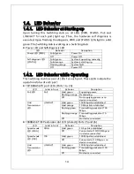
Upon turning this Switching Hub on, all LEDs (PWR, STATUS, PoE and
LINK/ACT for each port) light up. Then, the hardware self diagnosis is
executed. Upon finishing the diagnosis, PWR and STATUS LEDs light in solid
green. The Switching Hub is working as a Switching Hub.
Power LED and Self-diagnosis LED
LED
Behavior
Description
Power LED (PWR)
Solid green
Power On
Off
Power Off
Self-diagnosis LED
(STATUS)
Solid green
System is operating normally.
Solid orange
System is starting up.
Flashing orange
System fault.
Off
Power Off
1
1
.
.
4
4
.
.
2
2
.
.
L
L
E
E
D
D
B
B
e
e
h
h
a
a
v
v
i
i
o
o
r
r
w
w
h
h
i
i
l
l
e
e
O
O
p
p
e
e
r
r
a
a
t
t
i
i
n
n
g
g
This Switching Hub has a set of LEDs for each port. These LEDs indicate the
operation status of each port.
10/100BASE-TX port LEDs (Ports 1 to 24)
LED
Label in front
Behavior
Description
PoE LED
PoE
Solid green
Supplying power.
Flashing orange Overloading.
Off
Not supplying power or no
device connected.
Link/
Transmission
LED
LINK/ACT.
Solid green
100 Mbps link established.
Solid orange
10 Mbps link established.
Flashing green
Transmitting packets at 100
Mbps.
Flashing orange Transmitting packets at 10
Mbps.
Off
No device connected.
1000BASE-T/SFP extension slot LED (shared) (Ports 25 and 26)
LED
Label in front
Behavior
Description
Speed mode
LED (GIGA)
GIGA
Solid green
1 Gbps link established.
Off
Connected at 10/100 Mbps or
no device connected.
Speed mode
LED (100)
100
Solid green
100 Mbps link established.
Off
Connected at 10 Mbps or no
device connected.
Link/
Transmission
LED
LINK/ACT.
Solid green
100 Mbps link established.
Flashing green
Transmitting packets at 100
Mbps.
Off
No device connected.
Содержание M24PWR
Страница 5: ...5 malfunction When stacking Switching Hubs leave a minimum of 20 mm space between them is required ...
Страница 24: ...24 command If you enter a command or setting not available an error message is shown in the explanation field ...
Страница 26: ...26 ...
Страница 32: ...32 ...
Страница 45: ...45 ...
Страница 65: ...65 ...
Страница 74: ...74 Quit to previous menu Quits the Advanced Switch Configuration Menu and returns to the Main menu ...
Страница 77: ...77 setting and the management VLAN status of VLAN ID 1 is UP ...
Страница 92: ...92 Press S Q Return to the previous menu ...
Страница 94: ...94 ...
Страница 118: ...118 Q Return to the previous menu ...
Страница 121: ...121 ...
Страница 126: ...126 ICMP Type Displays the ICMP type ...
Страница 132: ...132 802 1p Priority Displays priority of IEEE802 1p TCP SYN Flag Displays the TCP SYN flag ICMP Type Displays ICMP type ...
Страница 152: ...152 Threshold Displays the threshold of the number of packets per second ...
Страница 169: ...169 Fig 4 7 49 Display of values accumulated after resetting the counters ...
Страница 181: ...181 Q Return to the previous menu ...
Страница 207: ...207 Q Return to the previous menu ...
Страница 228: ...228 RSTP MIB IEEE 802 1w IEEE8021 PAE MIB IEEE802 1X IEEE8023 LAG MIB IEEE 802 3ad ...
Страница 233: ...233 IEEE 802 3af standard ...


