background image

Note

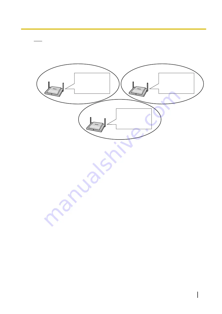
The floating extension number assigned to the ICD groups (e.g., 600) is used for calling multiple S-PSs
simultaneously.

SIP-CS
Ext.300 

PS Ring Group 600 
101 
102 
103 
105 

SIP-CS
Ext.301 

PS Ring Group 600 
101 
102 
103 
105 

SIP-CS
Ext.302 

PS Ring Group 600 
101 
102 
103 
105 

Installation Guide

59

4 Deployment Procedure

Содержание KX-UDS124

Страница 1: ...l Station Unit SIP Installation Guide Thank you for purchasing this Panasonic product Please read this manual carefully before using this product and save this manual for future use KX UDS124 Software File Version 01 300 or later ...

Страница 2: ...8 Tree Survey 49 4 9 Configuration and PS Registration for a system using a KX NS1000 51 4 9 1 Programming using Web Maintenance Console 51 4 9 2 Programming using the Web User Interface 56 4 9 3 Registering S PSs to the Super Master CS 57 4 9 4 Programming PS Ring Group 58 4 10 Configuration and PS Registration for a system using a third party SIP server 65 4 10 1 Programming SIP CSs for a Third ...

Страница 3: ...stalling or testing a SIP CS with an external AC adaptor the AC adaptor should be plugged into a wall outlet or floor mounted AC outlet Do not connect the AC adaptor to a ceiling mounted AC outlet as the weight of the adaptor may cause it to become disconnected Make sure that you do not short the battery or cables Never attempt to insert wires pins etc into the vents or other holes of the SIP CS D...

Страница 4: ...se only the optional AC adaptor KX A239CE PQLV206CE KX A239UK PQLV206E KX A239BX PQLV206CE KX A239EJ PQLV206E or KX A239AL PQLV206AL If damage to the SIP CS exposes any internal parts immediately disconnect the cable or cord If the power is supplied from the network to the SIP CS Power over Ethernet disconnect the Ethernet cables Otherwise disconnect the AC adaptor cord Then return the SIP CS to a...

Страница 5: ...health care facilities may be using equipment that could be sensitive to external RF radio frequency energy To ensure the security of private conversations only connect the SIP CS to a secure network To prevent unauthorised access only connect the SIP CS to a network that is properly managed Make sure all personal computers that are connected to the SIP CS employ up to date security measures To av...

Страница 6: ...lity we recommend that you initialise the SIP CS to erase all user data and restore the factory default settings before you dispose transfer or return the SIP CS Note In this manual the suffix of each model number e g KX UDS124CE is omitted unless necessary 6 Installation Guide 1 For Your Safety ...

Страница 7: ... municipality your waste disposal service or the point of sale where you purchased the items Penalties may be applicable for incorrect disposal of this waste in accordance with national legislation For business users in the European Union If you wish to discard electrical and electronic equipment please contact your dealer or supplier for further information Information on Disposal in other Countr...

Страница 8: ...For users in Hong Kong only HK0041200202 8 Installation Guide 1 For Your Safety ...

Страница 9: ...ommunication Handover Allows you to move between CS coverage areas during a conversation without disrupting the call This is only possible within the same Air Sync Group ICD Incoming Call Distribution ICD Group An incoming call distribution group receives calls directed to the group Incoming calls directed to an incoming call distribution group are distributed to the member extensions in the group...

Страница 10: ...ng an existing IP network infrastructure Air synchronisation technology is used for synchronising each SIP CS The SIP CS provides the following Wireless systems using a converged voice and data network infrastructure Wireless branch offices and wireless solutions by long distance installation on larger premises when located on the same network Reliable wireless communication using DECT technology ...

Страница 11: ...ng the call This is called Handover and is only possible within the same Air Sync Group You cannot move between Air Sync Groups during a conversation You can only move between Air Sync Groups when in idle status This is called Roaming Each Air Sync Group requires an Air Sync Master CS The system requires one Super Master CS to control the system as a whole The Air Sync Master CS of Air Sync Group ...

Страница 12: ...r Roaming Internet KX NS1000 SIP Server Note You can use an S PS in other systems sites if you register it to each system beforehand You can register an S PS to up to 4 systems Air Sync Groups at different sites connected by a dedicated line such as an IP VPN which share a Super Master CS and a SIP Server are considered part of the same system SIP Signalling and Media Stream Control Overview Movin...

Страница 13: ...ration to the SIP CS 2 RTP is transferred from SIP CS 1 to SIP CS 2 The S PS moves from the coverage area of SIP CS 2 to the coverage area of SIP CS 3 The S PS requests Location Registration to the SIP CS 3 RTP is transferred from SIP CS 1 to SIP CS 3 SIP signalling and the media stream are sent between the SIP CS currently in use and the SIP CS that was being used when the call started System Con...

Страница 14: ... Slave CSs in Air Sync Group 1 Note Data will be distributed until all Slave CSs in all Air Sync Groups receive the data Data is distributed in the following situations When the Super Master CS is started When All Save is performed through the Web user interface When Timed forwarding update is set When Timed phonebook importing is set System Specifications Specifications when connecting to a third...

Страница 15: ...For specifications when connecting to a KX NS1000 refer to the Installation Manual of the KX NS1000 Installation Guide 15 2 Overview ...

Страница 16: ... Stations Names and Locations LED Antennas CS ID Number ID xxxxxxxxxx RJ45 Modular RESET Switch DC Jack MAC Address Unpacking Unpack the box and check the items below SIP Cell Station 1 Screws 2 Washers 2 16 Installation Guide 3 Installing the SIP Cell Stations ...

Страница 17: ...lashing Starting up power on data link establishment Amber ON Stand by unstable synchronisation no active calls Slow amber flashing Talk unstable synchronisation active calls S PS data transfer 2 unstable synchronisation Moderate amber flashing Busy 1 unstable synchronisation Note LED flashing patterns are as follows Slow Flashing 60 times per minute Moderate Flashing 120 times per minute 1 All vo...

Страница 18: ...o connect the SIP CS to a switching hub The cable should be a 10BASE T 100BASE TX CAT 5 Category 5 or higher cable and the diameter of the cable must be 6 5 mm or less It is possible to connect the SIP CS to the LAN while registering the SIP CS to the SIP server 1 Connect the cable to the SIP CS Ethernet Cable 2 Pass the cable through the groove of the SIP CS in one of the following three ways To ...

Страница 19: ... AC adaptor should be plugged into a wall outlet or floor mounted AC outlet Do not connect the AC adaptor to a ceiling mounted AC outlet as the weight of the adaptor may cause it to become disconnected Note Use only the optional AC adaptor KX A239 for the SIP CS For details about the optional AC adaptor refer to AC Adaptor in 6 Appendix 1 Connect the AC adaptor cord to the SIP CS AC Adaptor Cord 2...

Страница 20: ...S and the cables should never be placed near or over a radiator or other heat source Do not bundle cables that are connected to the SIP CS with the AC power cords of machines located nearby Make sure the cables are securely fastened to the wall Notice Panasonic assumes no responsibility for injuries or property damage resulting from failures arising out of improper installation or operation incons...

Страница 21: ...ounting Please copy this page and use as a reference for wall mounting Install a screw here Install a screw here 83 mm Note Make sure to set the print size to correspond with the size of this page If the dimension of the paper output still deviates slightly from the measurement indicated here use the measurement indicated here Installation Guide 21 3 Installing the SIP Cell Stations ...

Страница 22: ...tain the distances listed below between equipment in order to prevent noise interference or the disconnection of a conversation The distance may vary depending on the environment Equipment Distance SIP CS and office equipment such as a computer telex fax machine etc More than 2 m SIP server and SIP CS More than 2 m SIP CS and other radio device More than 5 m Notice If multiple SIP CSs provide serv...

Страница 23: ...enance Tool installed on a PC connected to the same network This method provides a more accurate Tree Survey Refer to the SIP CS Maintenance Tool Guide for DECT SIP Cell Station Unit on the following web site for more information http panasonic net pcc support sipphone Notice If the Tree Survey is going to be conducted for 10 or more SIP CSs use the CS Maintenance Tool 5 Configuration Specify SIP ...

Страница 24: ...7 S PSs Area Check Check the service area sound quality and handover operation under actual conditions 24 Installation Guide 4 Deployment Procedure ...

Страница 25: ...r of levels can lead to instability in handover and air synchronisation The Master CS of Air Sync Group 1 is called the Super Master CS and controls the whole system CS Coverage Area for Air Synchronisation between SIP CSs The example below shows the size of the area where one SIP CS can synchronise with other SIP CSs if it is installed in an area with no obstacles B A C C Area Description A Very ...

Страница 26: ...e to each other can lead to interference and a reduction in the number of simultaneous calls In a regular office the average distance between SIP CSs should be approximately 30 m However since walls metallic shelves etc can weaken signals air synchronisation may not be as stable as planned Conduct a site survey after installing the SIP CSs as described in 4 3 Site Survey Understanding Radio Waves ...

Страница 27: ...ore than thick objects The table below shows the transmission tendency of radio waves when they reach objects made from various materials Object Material Transmission Tendency Wall Concrete The thicker they are the less radio waves penetrate them Ferroconcrete Radio waves can penetrate them but the more iron there is the more radio waves are reflected Window Glass Radio waves usually penetrate the...

Страница 28: ...S at a distance of about 30 m from the first SIP CS If you cannot maintain a distance of 30 m due to building limitations install the second SIP CS as far away as possible in the overlapping range of the air synchronisation coverage area Notice Locate SIP CSs so that places where most calls will be made are within the coverage area of as many SIP CSs as possible 3 When you have covered the necessa...

Страница 29: ...m 10 m Notice It may not be possible to create an Air Sync Group that spans multiple floors because the dividing ceilings may weaken the signal too much In this case locate a connecting SIP CS in the staircase between each floor Installation Guide 29 4 Deployment Procedure ...

Страница 30: ...hat is adjacent to most other SIP CSs in all 3 dimensions into the Master CS Air Synchronisation Air synchronisation assigns classifications to SIP CS and establishes connections based on those classifications This creates a robust system where the whole system is not reliant upon one SIP CS 30 Installation Guide 4 Deployment Procedure ...

Страница 31: ...w to Make a Site Map and write down the MAC address of each CS and radio signal values on the map LED Indications for Site Survey Mode SIP CS State Description Site Survey Mode Red and green alternate flashing Site Survey Master mode Slow green flashing The site survey signal being received is good Slow amber flashing The site survey signal being received is not good Slow red flashing The site sur...

Страница 32: ...r Source Site Survey Master Mode Site Survey Slave Mode LED Slow amber flashing LED Slow green flashing LED Red and green alternate flashing Confirming SIP CS Coverage Area for Establishing Conversations After confirming the SIP CS coverage area for air synchronisation confirm the speech quality The speech quality will be shown on the S PS s LCD Power Source Confirmed Location LED Red and green al...

Страница 33: ...l strength by the colour of the SIP CS s LED Confirming the Coverage Area for Air Synchronisation between SIP CSs 1 Turn on SIP CS 1 while holding the RESET switch 2 After the LED flashes red amber and green alternately release the RESET switch and then press the RESET switch again for about 1 second When SIP CS 1 enters Site Survey Master mode the LED of SIP CS 1 flashes red and green alternately...

Страница 34: ...alternate flashing 5 Place SIP CS 2 in the location planned for the SIP CS closest to the Air Sync Master CS currently SIP CS 1 Power Source Power Source SIP CS 1 SIP CS 2 Site Survey Slave Mode LED Slow red flashing 6 Confirm whether the LED of SIP CS 2 is green If it is not green move SIP CS 2 around to find a location where its LED turns green 34 Installation Guide 4 Deployment Procedure ...

Страница 35: ...1 SIP CS 2 Power Source SIP CS 1 SIP CS 2 Power Source LED Slow amber flashing LED Slow green flashing 7 Place SIP CS 1 where SIP CS 2 was and then place SIP CS 2 in the location planned for the SIP CS closest to current location of SIP CS 1 Power Source SIP CS 1 SIP CS 2 Power Source Confirmed Location LED Slow red flashing Installation Guide 35 4 Deployment Procedure ...

Страница 36: ...2 around to find a location where its LED turns green Power Source SIP CS 1 Power Source SIP CS 1 Power Source Power Source SIP CS 2 LED Slow amber flashing SIP CS 2 LED Slow green flashing 9 Repeat steps 7 to 8 for all other locations 36 Installation Guide 4 Deployment Procedure ...

Страница 37: ...ore Site Survey for S PS Service Area Checking the SIP CS ID Number Check the SIP CS ID number label attached to the SIP CS The SIP CS ID number is attached to the rear side of the SIP CS Starting the S PS in Maintenance Mode The S PS must be in Maintenance mode to conduct a site survey To enter Maintenance mode follow the procedure below Note Before using an S PS the battery must be inserted and ...

Страница 38: ...level and Error Rate are at acceptable levels you will continue hearing a tone from the S PS and 2 lines on the LCD of the S PS light green Note If there is an area where you cannot hear a tone and the 2 lines of the LCD do not light green relocate the SIP CS 6 After confirming the service area press POWER CANCEL key on the S PS to stop the tone 7 Relocate the SIP CS to another location 8 Walk aro...

Страница 39: ...be more than 8 and the error rate should be less than 2 Example Power Source Power Source Exiting Site Survey Master Mode While the SIP CS is in Site Survey Master Mode press the RESET switch to exit Installation Guide 39 4 Deployment Procedure ...

Страница 40: ...alternate flashing c CS Area Check using PS CS coverage area Power Source Plotting a map with the RSSI and Error Rate values makes perfoming the site survey easier You can check the map when changing the location of the CS 2 Confirm whether the LED of the Slave CS is now flashing green slowly If not move the Slave CS to a location where the LED is flashing green slowly After confirming the CS area...

Страница 41: ...2 MAC address3 MAC address9 PoE Hub 2 Write down the radio signal values RSSI and Error Rate around the next CS location and near important places such as meeting rooms on the map You can use this as a guide when changing the location of the CS Example of Site MAP 2 Radio signal conditions c CS coverage area Power Source CS Area Check using PS CS2 Location2 ٨CS2_Point1 RSSI 10 Error 01 CS1 Locatio...

Страница 42: ...subnet mask are as follows IP address 192 168 0 241 Subnet mask 255 255 255 0 Logging in to the Web User Interface 1 Connect a PC to the SIP CS intended to serve as the Super Master CS 2 Start a Web browser on the PC 3 Enter the default IP address of the SIP CS in the browser s address bar 4 Log in to the SIP CS as the administrator Note The default ID and password for the administrator are as fol...

Страница 43: ...ault gateway in Default Gateway 6 Enter the IP address of the primary DNS server in DNS1 7 Enter the IP address of a secondary DNS server in DNS2 8 Click Save Note After saving changes on the Basic Network Settings screen the changed settings will be applied when Complete appears after clicking Save The IP addresses of the SIP CSs may change if changes are made on the Basic Network Settings screen...

Страница 44: ...ep can be omitted for the Super Master CS 5 Click Save The SIP CS will restart automatically The SIP CS is now set as an Air Sync Master CS You may exit Site Survey Mode Changing the Administrator Password Note This setting is required only for the Super Master CS 1 In the System tab select Administrator Password 2 Enter the default password in Current Password 3 Enter a new password in New Passwo...

Страница 45: ...sed Connecting SIP CSs to the LAN Follow the procedure below to connect SIP CSs to the LAN 1 Disconnect the Super Master CS from the PC 2 Place the Super Master CS in its planned location and then connect it to the LAN 3 Turn the Super Master CS on 4 Place the other SIP CSs in their planned locations and then connect them to the LAN 5 Turn the SIP CSs on All the SIP CSs except Super Master CS will...

Страница 46: ...ering For the Super Master CS Provide a static IP address which can be used on your network For details refer to Assigning IP Address Information in 4 6 Basic Network Configuration For Air Sync Master CSs other than Super Master CS Set the IP address of the Super Master CS Set the IP address type DHCP or Static For Slave CSs Set the IP address type DHCP or Static For SIP CSs that have been used be...

Страница 47: ...n this case after the detected SIP CSs have been registered wait 5 minutes for the timeout display or click Stop CS Registration After registration check the CS Registered List to confirm that the SIP CSs have been registered Notice You cannot register the following SIP CSs SIP CSs that are not turned on SIP CSs that are not connected to the network SIP CSs for which no IP address has been set SIP...

Страница 48: ...p 3 select the maximum number of SIP CSs In this case after the detected SIP CSs have been registered wait 5 minutes for the timeout display or click Stop CS Registration After registration check the CS Registered List to confirm that the SIP CSs have been registered Notice After registering the SIP CS to the Air Sync Master CS when the SIP CS cannot connect to the Air Sync Master CS the LED of th...

Страница 49: ... synchronising CS from which the SIP CS will receive its clock signal The secondary synchronising CS is used as a backup so that if the primary synchronising CS fails the whole system will not be affected Air Sync Master CS Master Clock Signal Air Sync Master CS Master Clock Signal Radio Link Loss SIP CSs stop working Conducting the Tree Survey Note The result of the Tree Survey will be shown in a...

Страница 50: ...cel all SIP CSs will restart Manually adding a SIP CS at the End of the Connection Tree You can add SIP CSs at the end of the connection diagram manually This is useful when you want to expand the SIP CS coverage area 1 Register a SIP CS to the Air Sync Group for which you want to extend the SIP CS coverage area 2 Log in to the Super Master CS 3 In the System tab select Tree Survey 4 Select an Air...

Страница 51: ...ed to the KX NS1000 on the same LAN launch your Web browser and input the IP address of the PBX followed by the Web Maintenance Console port number into the address bar The default IP address for the LAN port of the PBX is 192 168 0 101 and the default Web Maintenance Console port number is 80 Accordingly the address to enter to connect to the PBX for the first time will be as follows enter the ad...

Страница 52: ... Total number of cards drop down list The selected number of cards will fill free virtual slots 4 Click OK Programming Extension Settings for S PSs The KX NS1000 assigns extension numbers to S PSs automatically However you can also specify desired extension numbers manually To assign extension numbers to S PSs manually follow the procedure below 52 Installation Guide 4 Deployment Procedure ...

Страница 53: ...xtension Card A menu will be shown under the mouse pointer 4 Click Port Property 5 Enter the desired extension number in the Extension Name column 6 Click OK Programming Extension Settings 1 Click Setup PBX Configuration Extension Wired Extension Extension Settings 2 Configure the extension name and required settings for the extension 3 Click OK Installation Guide 53 4 Deployment Procedure ...

Страница 54: ...ble Button 2 Programme the flexible buttons Note You can programme the following flexible buttons to S PSs For details about each flexible button refer to the Feature Guide of the KX NS1000 SCO DN LOGIN LOGOUT DSS CALLPARK WRAPUP ONETOUCH 3 Click OK 54 Installation Guide 4 Deployment Procedure ...

Страница 55: ...on number in the corresponding Extension Number cell Note It is recommended to use Web Maintenance Console in on line mode to change the extension number and password for the Super Master CS If the extension number and password of the Super Master CS are changed in off line mode the change may not take effect correctly In this case reset each SIP CS to let the change take effect correctly For deta...

Страница 56: ...isplay the menu of options and click Ins In service to set the card back to in service A configuration file for the system is created Note If you perform one of the following the configuration file will be re created Changing the V UTEXT32 card status from OUS to INS Restarting the KX NS1000 Changing the following settings Extension number Extension name Flexible button 4 9 2 Programming using the...

Страница 57: ...r SIP MLT default 7580 in Web Maintenance Console Do not enter any value in Standard File URL Product File URL or Master File URL 4 Click All Save The Super Master CS will start downloading the programmed information from the KX NS1000 4 9 3 Registering S PSs to the Super Master CS Registering S PSs to the Super Master CS Follow the procedure in Starting Registration Mode in 4 10 2 PS Registration...

Страница 58: ... of the KX NS1000 to program the following items Extension number setting Extension number must be assigned for all the SIP CSs Example SIP CS Ext 300 SIP CS Ext 302 SIP CS Ext 301 ICD group setting All the extension numbers assigned to the SIP CSs must be specified as members of an ICD group Example Floating extension no 600 Members 300 301 302 Extension numbers of the SIP CSs ICD Group 1 Floatin...

Страница 59: ...groups e g 600 is used for calling multiple S PSs simultaneously SIP CS Ext 300 PS Ring Group 600 101 102 103 105 SIP CS Ext 301 PS Ring Group 600 101 102 103 105 SIP CS Ext 302 PS Ring Group 600 101 102 103 105 Installation Guide 59 4 Deployment Procedure ...

Страница 60: ...bers 300 301 302 Extension numbers of the SIP CSs ICD Group 1 Floating extension no 601 Members 300 301 302 Extension numbers of the SIP CSs ICD Group 2 PS Ring Group 600 101 102 103 105 105 106 103 104 Incoming call To the extensions assigned to the ICD Group Incoming call To the extensions assigned to group 600 SIP CS Ext 300 SIP CS Ext 301 SIP CS Ext 302 60 Installation Guide 4 Deployment Proce...

Страница 61: ...amming a PS Ring Group with Web Maintenance Console of the KX NS1000 Assigning extension number to SIP CSs Assign extension numbers to the SIP CSs You can follow the same procedure as assigning extension numbers to KX UT series SIP phones For details about assigning extensions refer to the PC Programming Manual of the KX NS1000 Programming ICD groups When the S PSs that cover the desired area are ...

Страница 62: ...the Web User Interface of SIP CSs Assigning extension number to SIP CSs Assign the preconfigured extension number to each SIP CS that will be a member of the ICD group Logging in to a SIP CS You can log in to each SIP CS via the Web user interface of the Super Master CS 1 In the System tab select CS Management 62 Installation Guide 4 Deployment Procedure ...

Страница 63: ...t SIP Settings CS 2 Enter the SIP CS s extension number in Phone Number 3 Enter the SIP CS s extension number again in Authentication ID 4 Enter a password in Authentication Password 5 Click Save Programming a PS Ring Group of the SIP CS Assign the desired S PSs to a PS Ring Group of the SIP CS This setting can be performed only on the Web user interface of the Super Master CS Installation Guide 6...

Страница 64: ...istration for the group you want to programme 3 Select the S PSs to be registered in Available Users and then click To select all available S PSs click To deselect S PS s click or 4 Click All Save The changes are sent to all SIP CSs 64 Installation Guide 4 Deployment Procedure ...

Страница 65: ...CS is connected 1 In the VoIP tab select SIP Settings 2 In Registrar Server Address enter IP address of the SIP Registrar server 3 In Registrar Server Port enter the port number of the SIP Registrar server that is set to communicate with the SIP CS 4 In Proxy Server Address enter the IP address of the SIP Proxy server 5 In Proxy Server Port enter the port number of the SIP Proxy server that is set...

Страница 66: ...ences select a codec to use and specify its priority 3 Click All Save 4 10 2 PS Registration This section shows how to register S PS by using Web user interface Log in to the Web User Interface of the Super Master CS Please refer to Logging in to the Web User Interface in 4 6 Basic Network Configuration for entering Web user interface 66 Installation Guide 4 Deployment Procedure ...

Страница 67: ...n names to the S PSs 1 In the System tab select PS Registration 2 Enter an extension name in PS Name 3 Click All Save 4 Select Line 1 SIP Setting or Line 2 SIP Setting Note Some SIP servers allow only 1 extension number per telephone For details refer your SIP server s documentation Installation Guide 67 4 Deployment Procedure ...

Страница 68: ... the procedure below to register S PSs 1 In the System tab select PS Registration Start PS Registration 2 Select the S PSs to be registered in Available PS and then click To select all available S PSs click To deselect S PS s click or 3 Click Next 4 Click OK to confirm registration Registering S PSs After entering PS Registration mode follow the procedure below to register each S PS For unregister...

Страница 69: ...PSs perform the registration procedure on each S PS individually Performing the registration procedure on multiple S PSs at the same time may result in an error In this case reperform the registration procedure After registering S PSs the Web port will be closed Refer to the Administrator Guide to open the Web port again After registering S PSs S PS firmware update may start automatically During t...

Страница 70: ...check the registration status of each S PS in the Wireless Status field If PS Registration Complete is displayed on the left of the screen all S PSs that selected for registration were registered successfully Unregistering S PSs If you want to unregister a specified S PS follow the procedure below 70 Installation Guide 4 Deployment Procedure ...

Страница 71: ...edure was performed you must unregister the base system manually 1 Enter the Setting Handset menu 2 Select System Option and then press Tone Option System Option Other Option 3 Select Cancel Base and then press Register H S Cancel Base Select Base System Lock Change PIN 4 Select the base number for unregistration by pressing and then press Note You can select multiple base numbers for unregistrati...

Страница 72: ...p of Super Master CS configuration data The backup data is useful when restoring the same configuration data to the Super Master CS when it must be re installed due to a hardware error etc For details please refer to the Administrator Guide 72 Installation Guide 4 Deployment Procedure ...

Страница 73: ...e service area listening to the tone from S PS 1 s receiver to confirm voice quality and handover operation The CS ID and signal strength of the SIP CS you are connected to and the target SIP CS for Handover is displayed on the S PS When the signal strength is sufficiently strong the CS ID is displayed in green CSnnn xx yy Detected CS IDs and RSSI level are displayed If the RSSI level exceeds the ...

Страница 74: ... other SIP CS s RSSI level Make sure to check that there is no noise during handover Exiting S PS Area Check Mode When the S PS area check is finished exit the S PS area check mode 1 Start the S PS in Maintenance mode For details see Starting the S PS in Maintenance Mode in 4 3 Site Survey 2 Select PS area check and then press 3 Select Off 4 Press 5 Press the POWER key until the S PS is turned off...

Страница 75: ...CP server and so on Tree Survey Error Messages and Notices When an error occurs during or after the Tree Survey an error message or notice is displayed Messages displayed during the Tree Survey Message Probable Cause Solution Tree Survey Timeout Slave CS may have network trouble Slave CS cannot receive radio signal from another Air Sync Group CS Please check the SIP CS s power network condition Pl...

Страница 76: ...e distance between the S PS and the SIP CS is too far PS Registration mode of the SIP CS did not start or was timed out Note For more information about registering the S PS refer to the documentation for the S PS 32 S PSs are already registered Note You can register up to 32 S PSs to one SIP CS by default If you want to register an S PS to a SIP CS which already has 32 S PSs registered re register...

Страница 77: ...lls 4 Power Supply PoE IEEE 802 3af Class1 Optional AC adaptor KX A239CE PQLV206CE KX A239UK PQLV206E KX A239BX PQLV206CE KX A239EJ PQLV206E KX A239AL PQLV206AL VoIP Audio Codec G 722 G 711 G 729A G 726 LAN Port 10 BASE T 100 BASE TX VLAN Yes 802 1Q IP Addressing DHCP Static IP Address Setting Software Upgrade Yes Built in VPN No Weight 290 g Size W 190 mm H 133 9 mm D 39 3 mm PS Specification Ite...

Страница 78: ... of dust moisture high temperature more than 40 C low temperature less than 0 C and vibration and should not be exposed to direct sunlight The SIP CS should not be placed outdoors use indoors The SIP CS should not be placed near high voltage equipment The SIP CS should not be placed on a metal object Compatible S PSs Item Model No S PS KX UDT111 KX UDT121 KX UDT131 Note For more details about S PS...

Страница 79: ...Model No Part No Type KX A239CE PQLV206CE KX A239BX KX A239UK PQLV206E KX A239EJ KX A239AL PQLV206AL Installation Guide 79 6 Appendix ...

Страница 80: ...at the KX UDS124CE is in compliance with the essential requirements and other relevant provisions of Radio Telecommunications Terminal Equipment R TTE Directive 1999 5 EC Declarations of Conformity for the relevant Panasonic products described in this manual are available for download by visiting http www doc panasonic de Contact to Authorised Representative Panasonic Testing Centre Panasonic Mark...

Отзывы: