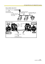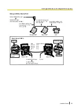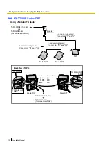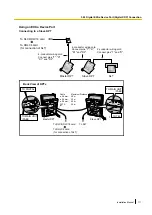
Note for KX-T7765 Users
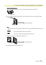
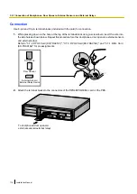
When loosening/tightening the screw, do not scratch the cabinet wall with the driver shaft.
Cabinet Wall
2.
Pass the wires through the hole in the base cover, and attach the base cover to a wall using 2 screws.
Screw
To 8-pin terminal block
Note
Two kinds of screws are included with the doorphone. Please choose the appropriate kind for your wall
type.
: when a doorphone plate has been fixed to the wall
: when you wish to install the doorphone directly onto the wall
3.
Connect the wires to the screws located in the back cover.
To 8-pin terminal block
4.
Re-attach the 2 halves and re-insert the screw.
Installation Manual
115
3.9.1 Connection of Doorphones, Door Openers, External Sensors, and External Relays
Содержание KX-NCP1000
Страница 42: ...42 Installation Manual 2 1 3 Activation Key File ...
Страница 52: ...Connector Type Pin Number Used for Mini Plug 2 4 IPCMPR 52 Installation Manual 3 2 5 Types of Connectors ...
Страница 134: ...134 Installation Manual 4 3 1 Installing and Starting the Maintenance Console ...
Страница 146: ...146 Installation Manual 5 1 5 Troubleshooting by Error Log ...
Страница 147: ...Section 6 Appendix Installation Manual 147 ...
Страница 151: ...Index Installation Manual 151 ...

