


– 5-5 –
5.2. Baseband Overview
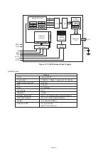
5.2.1. Baseband Block Diagram
The Baseband circuits of the phone are required to perform the following functions:
8
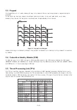
Equalisation
8
Channel coding / decoding
8
Speech coding / decoding
8
Data Encryption
8
Layer 1, 2 and 3 software tasks
8
Man Machine interface (MMI)
8
System Interface
8
SIM Interface and Management
8
Audio and 32 Strings Melody Generation
8
Power supply and battery management
8
RF power control
8
Synchronization
8
Real time clock
8
Camera
Figure 5.4. Baseband Block Diagram
The EB-X100 Baseband is built around a U2 GSM baseband LSI. One chip (Calypso_G2) carries out signal processing with
DSP and CPU, and the U3 (IOTA) provides the analogue interface. The highly integrated nature of the chips means that each
can contain a large number of functions.
RF I/F
SIM interface
Voice band interface
Baseband interface
RF digital control lines
I and Q lines
AFC
Power ramp signal
J6
Speaker
Melody control lines
Key pad interface
UART
+
-
J1
Camera
Module
CON1
SIM CONN
CON 1
Earphone Jack
J6
Receiver
MIC1
Microphone
U3
IOTA
U2
Calypso
G2_Lite
LCM
U10
Flash+S
RAM
U8
Backend
IC
Keypad
RTC
(32 kHz)
J4
Battery
J5
IO_Connector
U17
Melody IC
M1
Vibrator
BT1
RTC
Battery
T
Содержание EB-X100
Страница 68: ... 8 19 ...
Страница 69: ... 8 20 ...


