9
GETTING STARTED
SAFETY / SPECIFICATIONS
ASSEMBLY / INSTALLATION
OPERATION
TROUBLESHOOTING
MAINTENANCE / REPAIR
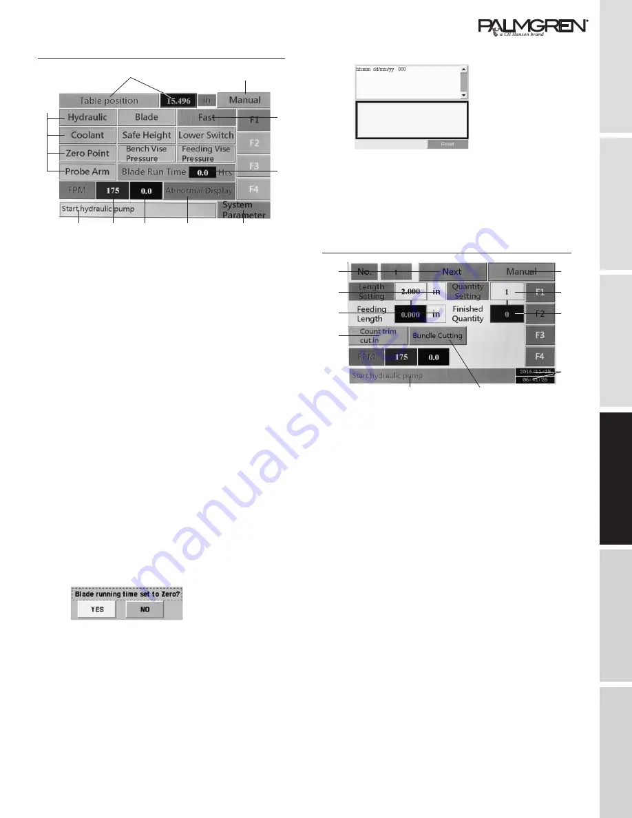
Interface Control Screen - Main (Home) Menu - F1
1
2
5
4
6
7
8
9
10
3
Touch F1 button to display the screen shown above.
1. Feeding vise move position
The numeric column shows shuttle vise moving position.
Zero (Home) Setting:
This allows you to set the feeding vise zero position
before executing automatic cutting when machine power
has been shut Off then turned On again.
Executing the zero setting should done be after clamping
the front vise and opening the rear vise in the manual
mode.
2. Operate mode
Shows machine operation mode: Manual or Auto.
3. Working indicator lights
The indicator lights show the current working status
including Hydraulic, Blade Tension, Coolant, Work Light,
Safe Height, Lower Limit Switch, Zero Point, Bench Vise
Pressure, Shuttle Vise Pressure and Probe Arm Limit
Switch.
4. Feeding (Shuttle) Vise Speed
Touching this button toggles the Feeding Vise between
Fast and Slow feed rates.
5. Blade running time
Shows blade running time. Touch “YES” to start counting
or zero setting after blade has been changed.
Touch the blade run time
column to set the blade run
time to zero, YES or NO.
6 A password is required to enter into this section. After the
password is entered the Parameter Settings will appear.
This page has already been set with default parameters
before shipping. To enter this page you must key in the
password and hit ENT. It is not necessary to make any
changes in the parameter settings.
Parameter changes should be only be made by a
qualified personnel or distributor. Caution should be
taking when making any changes in system parameters,
because they can cause a malfunction in machine
operation.
7. The Alarm Display Shows error notices when machine
malfunctions occur and
how to solve them.
This page also records
the history alarm data.
Check the error data by
moving right side vertical
and horizontal arrow
signs. (See pg. 19 for
Troubleshooting help)
8. Shows actual running blade speed.
9. Set the blade speed.
Touch to set blade speed directly and quickly.
10. Machine Execution Message.
Interface Control Screen - Current Operations - F2
11
20
19
18
12
13
14
15
16
17
Touch the F2 button to display the screen shown above.
11. Execution Number
Refers to the instruction task order. Touch it to go to
page F3 “Material Cutting Jobs.” Touch next to display
the next job.
12. Operation mode
Shows machine execution mode: Manual or Automatic.
13. Quantity Setting
Shows the quantity setting of the current instruction task
that are to be completed.
14. Finished Quantity
Shows the finished quantity of the current instruction task
that have been completed.
15. Date and Time
16. Single Cutting or Bundle Cutting
Touch this button to choose Single or Bundle Cutting.
For Single Cutting operation, the Feeding (Shuttle) Vise
will clamp at a position in the back to prepare for the next
feed.
When bundle cutting is selected the Feeding (Shuttle)
Vise will stay at the front position after feeding material
forward.
17. Machine Execution Message
(Continues on next page)


