SECTION 5
SERVICE
Pacific Power Source ©2013
5-1
Document # 126050-10 Rev E
5.0 MAINTENANCE
The MS-Series equipment has been designed so that maintenance is kept to an
absolute minimum. This section describes the maintenance requirements of this
equipment. Paragraph 5.1 describes the maintenance required by the Power
Source. If there are any questions please call Pacific Power Source, Inc. at 800-
854-2433 in the United States. For international support dial 1-949-251-1800.
5.1
MAINTENANCE SCHEDULE
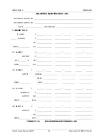
Routine maintenance of the MS equipment consists of the steps below. Pacific
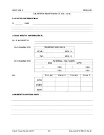
recommends the use of a maintenance checklist of the form shown in FIGURE
5.1.3. to help guarantee regular performance of maintenance. Additionally,
equipment history is then created. This is sometimes helpful when servicing the
equipment, particularly when attempting to solve an application type problem.
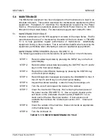
MAINTENANCE PROCEDURES (Refer to FIGURE 5.1.3)
The following procedure is recommended to be performed at 3 month intervals.
STEP 1:
Record cabinet input data by pressing the INPUT key on the front
panel display.
STEP 2:
Record cabinet output data by pressing the OUTPUT then f1 and f2
keys on the front panel display.
STEP 3:
Record the current Status message by pressing the STATUS key
on the front panel display.
STEP 4:
Record Diagnostic messages by pressing the DIAGNOSTIC then f1
then f2 then f3 and f4 keys on the front panel display.
STEP 5:
Inspect the cabinet carefully. Listen for noisy fan bearings, etc.
STEP 6:
Turn the unit off and inspect the inside of the cabinet
STEP 7:
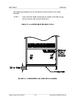
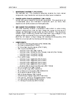
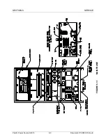
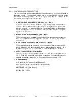
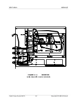
Clean the Inverter Air Filters by, first, removing the back panel of
the power source (FIGURE 5.1.1). Use a vacuum cleaner and a
soft brush on the underside of each inverter (FIGURE 5.1.2) to
clean each of the two filters per inverter. If rear access is not
available then remove the inverters per section 6.5.1. Clean and
replace.
STEP 8:
Clean the outside of the machine. Make comments as appropriate
in the maintenance log.
STEP 9:
Turn the unit back on.
TABLE 5.1.1 6 MONTH MAINTENANCE CYCLE
Содержание MS SERIES
Страница 1: ...MS SERIES AC POWER SOURCE OPERATIONS MANUAL PACIFIC POWER SOURCE ...
Страница 4: ...THIS PAGE INTENTIONALLY BLANK ...
Страница 19: ...SECTION 2 SPECIFICATIONS Pacific Power Source 2013 2 4 Document 126050 10 Rev E FIGURE 2 2 OUTLINE DRAWING ...
Страница 65: ...SECTION 4 OPERATION Pacific Power Source 2013 4 25 Document 126050 10 Rev E FIGURE 4 5 CABINET ASSEMBLY ...
Страница 84: ...SECTION 6 SERVICE Pacific Power Source 2013 6 3 Document 126050 10 Rev E FIGURE 6 1 1 MAINFRAME ...
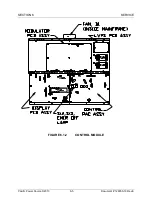
Страница 86: ...SECTION 6 SERVICE Pacific Power Source 2013 6 5 Document 126050 10 Rev E FIGURE 6 1 2 CONTROL MODULE ...
Страница 103: ...SECTION 6 SERVICE Pacific Power Source 2013 6 22 Document 126050 10 Rev E FIGURE 6 3 1 PERFORMANCE CHECK FLOW CHART ...
Страница 106: ...SECTION 6 SERVICE Pacific Power Source 2013 6 25 Document 126050 10 Rev E FIGURE 6 3 3 DISPLAY FLOW CHART ...
Страница 108: ...SECTION 6 SERVICE Pacific Power Source 2013 6 27 Document 126050 10 Rev E FIGURE 6 3 4 EMER OFF FLOW CHART ...
Страница 110: ...SECTION 6 SERVICE Pacific Power Source 2013 6 29 Document 126050 10 Rev E FIGURE 6 3 5 NO INVERTER VOLTAGE FLOW CHART ...
Страница 112: ...SECTION 6 SERVICE Pacific Power Source 2013 6 31 Document 126050 10 Rev E FIGURE 6 3 6 ABNORMAL VOLTS FLOW CHART ...
Страница 114: ...SECTION 6 SERVICE Pacific Power Source 2013 6 33 Document 126050 10 Rev E FIGURE 6 4 2 INPUT POWER SCHEMATIC ...
Страница 115: ...SECTION 6 SERVICE Pacific Power Source 2013 6 34 Document 126050 10 Rev E FIGURE 6 4 3 DC POWER SUPPLY SCHEMATIC ...
Страница 130: ...APPENDIX B SYSTEM SCHEMATIC Pacific Power Source 2013 B 1 Document 126050 10 Rev E FIGURE B 1 3060 MS SYSTEM SCHEMATIC ...

