SECTION 1
GENERAL
Pacific Power Source ©2013
1-4
Document # 126050-10 Rev E
1.5
DEFINITIONS
Common terms and component names, as used throughout this MS-Series
manual are defined below:
Power Source
All components functioning together which convert input AC
power to isolated, conditioned, variable frequency and variable
voltage output AC power to the load.
Cabinet
One enclosure that contains a Power Source.
System
One or more enclosures which make up a paralleled cabinet
power source.
Rectifier
The circuit component that contains the equipment and controls
necessary to convert the input AC power to DC power.
Inverter
The circuit component that contains the equipment and controls
necessary to convert DC power from the rectifier to AC power
required by the load. A high frequency pulse-width modulated
switcher.
Internal
Control
System
The signal processing circuits that regulate the power
conversion processes, detect fault conditions, and control the
sequence of operation of the Power Source. This term may be
shortened to "Control System."
Operator
Controls
The controls which are used by the operator to monitor and
operate the Power Source. They are located on the front of the
cabinet exterior.
Input Power
Power provided by the electrical utility company, or auxiliary
generator, connected to the input of the Power Source.
Output Power
Power provided by the Power Source to the load, connected to
the output of the Power Source.
Содержание MS SERIES
Страница 1: ...MS SERIES AC POWER SOURCE OPERATIONS MANUAL PACIFIC POWER SOURCE ...
Страница 4: ...THIS PAGE INTENTIONALLY BLANK ...
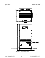
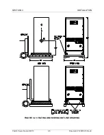
Страница 19: ...SECTION 2 SPECIFICATIONS Pacific Power Source 2013 2 4 Document 126050 10 Rev E FIGURE 2 2 OUTLINE DRAWING ...
Страница 65: ...SECTION 4 OPERATION Pacific Power Source 2013 4 25 Document 126050 10 Rev E FIGURE 4 5 CABINET ASSEMBLY ...
Страница 84: ...SECTION 6 SERVICE Pacific Power Source 2013 6 3 Document 126050 10 Rev E FIGURE 6 1 1 MAINFRAME ...
Страница 86: ...SECTION 6 SERVICE Pacific Power Source 2013 6 5 Document 126050 10 Rev E FIGURE 6 1 2 CONTROL MODULE ...
Страница 103: ...SECTION 6 SERVICE Pacific Power Source 2013 6 22 Document 126050 10 Rev E FIGURE 6 3 1 PERFORMANCE CHECK FLOW CHART ...
Страница 106: ...SECTION 6 SERVICE Pacific Power Source 2013 6 25 Document 126050 10 Rev E FIGURE 6 3 3 DISPLAY FLOW CHART ...
Страница 108: ...SECTION 6 SERVICE Pacific Power Source 2013 6 27 Document 126050 10 Rev E FIGURE 6 3 4 EMER OFF FLOW CHART ...
Страница 110: ...SECTION 6 SERVICE Pacific Power Source 2013 6 29 Document 126050 10 Rev E FIGURE 6 3 5 NO INVERTER VOLTAGE FLOW CHART ...
Страница 112: ...SECTION 6 SERVICE Pacific Power Source 2013 6 31 Document 126050 10 Rev E FIGURE 6 3 6 ABNORMAL VOLTS FLOW CHART ...
Страница 114: ...SECTION 6 SERVICE Pacific Power Source 2013 6 33 Document 126050 10 Rev E FIGURE 6 4 2 INPUT POWER SCHEMATIC ...
Страница 115: ...SECTION 6 SERVICE Pacific Power Source 2013 6 34 Document 126050 10 Rev E FIGURE 6 4 3 DC POWER SUPPLY SCHEMATIC ...
Страница 130: ...APPENDIX B SYSTEM SCHEMATIC Pacific Power Source 2013 B 1 Document 126050 10 Rev E FIGURE B 1 3060 MS SYSTEM SCHEMATIC ...


