SECTION 6
SERVICE
Pacific Power Source ©2013
6-28
Document # 126050-10 Rev E
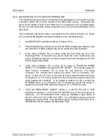
6.3.5 NO-INVERTER-VOLTS SERVICE PROCEDURE
The troubleshooting procedure contained in this paragraph is to be used to locate
a problem within the Inverter circuits of the MS power source. Directions are
given which locate a fault to the PCB level or component level as appropriate.
Do not use this procedure unless instructed to do so by the performance check
flow chart.
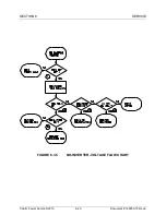
The numbered comments below correspond to the circled numbers on figure
6.3.5 and provide detailed instructions relative to the referenced step.
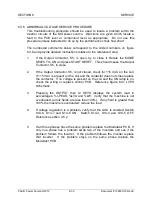
1.
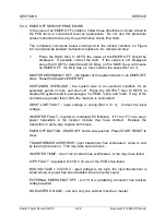
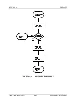
If an EMER OFF condition exists go to figure 6.3.4.
2.
Press the DIAG then f3 keys and verify the BUS voltages are between 160
and 240 VDC. If BUS voltages are not ok check the input contactor.
3.
If the input contactor, S3, is closed verify two red LEDs are lit on the
Discharge PCB. If the LED's are not lit check the Input Transformer and
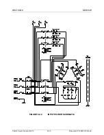
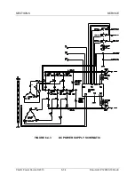
wiring. Reference figure 6.4.2 Input Power Schematic and figure 6.4.3 DC
Power Supply Schematic.
4.
If the Input Contactor, S3, is open, try to close it. Rotate the MODE
SELECT to STANDBY and press START RESET. This should cause the
Slow Turn-on Contactor, S7, to close for one second. The Input
Contactor, S3, should close before the Slow Turn-on Contactor, S7,
opens. Check for 115 VAC on the coils of these contactors during the turn
on sequence. If 115 VAC is present on the coil and the contactor does not
close replace the contactor. If no voltage is present on the coil and the
STANDBY lamp is on during the turn on sequence, check the wiring or
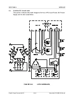
replace the Control PCB. Reference figure 6.4.1 LVPS Schematic.
5.
Verify the FREQUENCY SELECT switch is in the 50, 60, 400 or VAR
positions as desired. Turn the VOLTS ADJUST pot, on the front panel, to
maximum. On the Modulator PCB, verify an Oscillator signal exists of
about 5 VAC on C107, C207 and C307. If no Oscillator signal is present
replace the Control PCB. If an Oscillator signal is present and there is no
INVERTER VOLTS replace the Modulator PCB.
Содержание MS SERIES
Страница 1: ...MS SERIES AC POWER SOURCE OPERATIONS MANUAL PACIFIC POWER SOURCE ...
Страница 4: ...THIS PAGE INTENTIONALLY BLANK ...
Страница 19: ...SECTION 2 SPECIFICATIONS Pacific Power Source 2013 2 4 Document 126050 10 Rev E FIGURE 2 2 OUTLINE DRAWING ...
Страница 65: ...SECTION 4 OPERATION Pacific Power Source 2013 4 25 Document 126050 10 Rev E FIGURE 4 5 CABINET ASSEMBLY ...
Страница 84: ...SECTION 6 SERVICE Pacific Power Source 2013 6 3 Document 126050 10 Rev E FIGURE 6 1 1 MAINFRAME ...
Страница 86: ...SECTION 6 SERVICE Pacific Power Source 2013 6 5 Document 126050 10 Rev E FIGURE 6 1 2 CONTROL MODULE ...
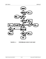
Страница 103: ...SECTION 6 SERVICE Pacific Power Source 2013 6 22 Document 126050 10 Rev E FIGURE 6 3 1 PERFORMANCE CHECK FLOW CHART ...
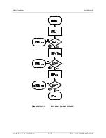
Страница 106: ...SECTION 6 SERVICE Pacific Power Source 2013 6 25 Document 126050 10 Rev E FIGURE 6 3 3 DISPLAY FLOW CHART ...
Страница 108: ...SECTION 6 SERVICE Pacific Power Source 2013 6 27 Document 126050 10 Rev E FIGURE 6 3 4 EMER OFF FLOW CHART ...
Страница 110: ...SECTION 6 SERVICE Pacific Power Source 2013 6 29 Document 126050 10 Rev E FIGURE 6 3 5 NO INVERTER VOLTAGE FLOW CHART ...
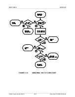
Страница 112: ...SECTION 6 SERVICE Pacific Power Source 2013 6 31 Document 126050 10 Rev E FIGURE 6 3 6 ABNORMAL VOLTS FLOW CHART ...
Страница 114: ...SECTION 6 SERVICE Pacific Power Source 2013 6 33 Document 126050 10 Rev E FIGURE 6 4 2 INPUT POWER SCHEMATIC ...
Страница 115: ...SECTION 6 SERVICE Pacific Power Source 2013 6 34 Document 126050 10 Rev E FIGURE 6 4 3 DC POWER SUPPLY SCHEMATIC ...
Страница 130: ...APPENDIX B SYSTEM SCHEMATIC Pacific Power Source 2013 B 1 Document 126050 10 Rev E FIGURE B 1 3060 MS SYSTEM SCHEMATIC ...

