SECTION 6
SERVICE
Pacific Power Source ©2013
6-8
Document # 126050-10 Rev E
6.2
THEORY OF OPERATION
The basic theory of operation for the MS-Series Power Source is defined in the
information which follows and is provided as technical reference to aid any
troubleshooting of the equipment.
The MS-Series Power Source consists of five basic subsystems which are as
follows:
1.
Power Conversion Circuits (Paragraph 6.2.1)
2.
System Control Circuits (Paragraph 6.2.2)
3.
DC Power Supply Circuits (Paragraph 6.2.3)
4.
Metering and Display Circuits (Paragraph 6.2.4)
5.
Paralleling Circuits (Paragraph 6.2.5)
Each of the circuits is discussed in detail in each of the above referenced
paragraphs.
When the DIAG then f4 keys are pressed the status inputs to the Display PCB
are displayed (Reference section 4.3.1.4). This display may be used to
determine the state of control terms in the system.
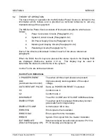
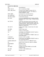
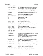
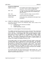
Control Terms are defined as follows:
Control Term Definitions
3 PHASE PRESENT
True when all three input phases are present.
AGC
(Automatic Gain Control)
Improves steady state regulation of the output
voltage.
AUTO RESTART PULSE
Same as POWER ON RESET if selected.
C0
Control mode 0.
C2
Control mode 2.
DISCHARGE
True if S3 CLOSE and S7 CLOSE COMM are false.
EMER OFF SW
True when switch is pressed. Momentary contact
panel switch with integral lamp.
EMER OFF LAMP
Is lit whenever Q6 is true.
ERROR IN
Error signal to the modulator.
ERROR OUT
Error signal from the modulator.
ERROR
System Error signal from the master modulator.
EXT EMER OFF
(External Emergency Off)
External contacts have shorted connector P1-18 to
P1-19 causing an emergency off.
Содержание MS SERIES
Страница 1: ...MS SERIES AC POWER SOURCE OPERATIONS MANUAL PACIFIC POWER SOURCE ...
Страница 4: ...THIS PAGE INTENTIONALLY BLANK ...
Страница 19: ...SECTION 2 SPECIFICATIONS Pacific Power Source 2013 2 4 Document 126050 10 Rev E FIGURE 2 2 OUTLINE DRAWING ...
Страница 65: ...SECTION 4 OPERATION Pacific Power Source 2013 4 25 Document 126050 10 Rev E FIGURE 4 5 CABINET ASSEMBLY ...
Страница 84: ...SECTION 6 SERVICE Pacific Power Source 2013 6 3 Document 126050 10 Rev E FIGURE 6 1 1 MAINFRAME ...
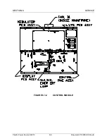
Страница 86: ...SECTION 6 SERVICE Pacific Power Source 2013 6 5 Document 126050 10 Rev E FIGURE 6 1 2 CONTROL MODULE ...
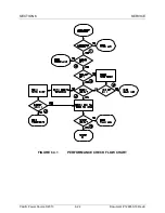
Страница 103: ...SECTION 6 SERVICE Pacific Power Source 2013 6 22 Document 126050 10 Rev E FIGURE 6 3 1 PERFORMANCE CHECK FLOW CHART ...
Страница 106: ...SECTION 6 SERVICE Pacific Power Source 2013 6 25 Document 126050 10 Rev E FIGURE 6 3 3 DISPLAY FLOW CHART ...
Страница 108: ...SECTION 6 SERVICE Pacific Power Source 2013 6 27 Document 126050 10 Rev E FIGURE 6 3 4 EMER OFF FLOW CHART ...
Страница 110: ...SECTION 6 SERVICE Pacific Power Source 2013 6 29 Document 126050 10 Rev E FIGURE 6 3 5 NO INVERTER VOLTAGE FLOW CHART ...
Страница 112: ...SECTION 6 SERVICE Pacific Power Source 2013 6 31 Document 126050 10 Rev E FIGURE 6 3 6 ABNORMAL VOLTS FLOW CHART ...
Страница 114: ...SECTION 6 SERVICE Pacific Power Source 2013 6 33 Document 126050 10 Rev E FIGURE 6 4 2 INPUT POWER SCHEMATIC ...
Страница 115: ...SECTION 6 SERVICE Pacific Power Source 2013 6 34 Document 126050 10 Rev E FIGURE 6 4 3 DC POWER SUPPLY SCHEMATIC ...
Страница 130: ...APPENDIX B SYSTEM SCHEMATIC Pacific Power Source 2013 B 1 Document 126050 10 Rev E FIGURE B 1 3060 MS SYSTEM SCHEMATIC ...

