SECTION 4
OPERATION
Pacific Power Source ©2013
4-14
Document # 126050-10 Rev E
4.3.1.7 SPECIAL KEY COMBINATIONS
INPUT/
STATUS/
HELP:
Pressed simultaneously shall cause a software
reset of the display CPU.
OUTPUT/
DIAG/
ALARM:
Pressed simultaneously shall clear the RAM.
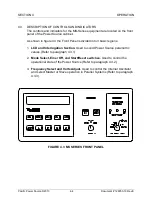
4.3.2 MODE SELECT, EMERGENCY OFF, AND ON-RESET SWITCHES
As the name implies, these switches control the operational mode of the Power
Source. The operator must be fully familiar with these switches and their function
prior to operating the Power Source.
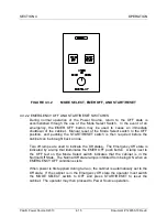
4.3.2.1 MODE SELECT SWITCH
During normal operation of the MS, control of the cabinet is through the MODE
SELECT switch. The design of the switch is such that only one Mode Position
can occur at any time. The three available switch positions are defined as
follows:
OFF
The cabinet is shut off. No power is supplied to the load. A red
LED next to the OFF position is lighted when there is no power
applied to the output and diagnostic checks are OK.
STANDBY
The cabinet is in the Standby State. The internal high voltage
power supplies are energized. The inverter is operating. The
cabinet is ready to deliver output power but the output contactor
is open. A red LED next to the STANDBY position is lighted.
ON
The output terminals are energized. The output contactor is
closed and supplying power to the load. A red LED next to the
ON position is lighted.
Содержание MS SERIES
Страница 1: ...MS SERIES AC POWER SOURCE OPERATIONS MANUAL PACIFIC POWER SOURCE ...
Страница 4: ...THIS PAGE INTENTIONALLY BLANK ...
Страница 19: ...SECTION 2 SPECIFICATIONS Pacific Power Source 2013 2 4 Document 126050 10 Rev E FIGURE 2 2 OUTLINE DRAWING ...
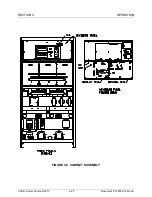
Страница 65: ...SECTION 4 OPERATION Pacific Power Source 2013 4 25 Document 126050 10 Rev E FIGURE 4 5 CABINET ASSEMBLY ...
Страница 84: ...SECTION 6 SERVICE Pacific Power Source 2013 6 3 Document 126050 10 Rev E FIGURE 6 1 1 MAINFRAME ...
Страница 86: ...SECTION 6 SERVICE Pacific Power Source 2013 6 5 Document 126050 10 Rev E FIGURE 6 1 2 CONTROL MODULE ...
Страница 103: ...SECTION 6 SERVICE Pacific Power Source 2013 6 22 Document 126050 10 Rev E FIGURE 6 3 1 PERFORMANCE CHECK FLOW CHART ...
Страница 106: ...SECTION 6 SERVICE Pacific Power Source 2013 6 25 Document 126050 10 Rev E FIGURE 6 3 3 DISPLAY FLOW CHART ...
Страница 108: ...SECTION 6 SERVICE Pacific Power Source 2013 6 27 Document 126050 10 Rev E FIGURE 6 3 4 EMER OFF FLOW CHART ...
Страница 110: ...SECTION 6 SERVICE Pacific Power Source 2013 6 29 Document 126050 10 Rev E FIGURE 6 3 5 NO INVERTER VOLTAGE FLOW CHART ...
Страница 112: ...SECTION 6 SERVICE Pacific Power Source 2013 6 31 Document 126050 10 Rev E FIGURE 6 3 6 ABNORMAL VOLTS FLOW CHART ...
Страница 114: ...SECTION 6 SERVICE Pacific Power Source 2013 6 33 Document 126050 10 Rev E FIGURE 6 4 2 INPUT POWER SCHEMATIC ...
Страница 115: ...SECTION 6 SERVICE Pacific Power Source 2013 6 34 Document 126050 10 Rev E FIGURE 6 4 3 DC POWER SUPPLY SCHEMATIC ...
Страница 130: ...APPENDIX B SYSTEM SCHEMATIC Pacific Power Source 2013 B 1 Document 126050 10 Rev E FIGURE B 1 3060 MS SYSTEM SCHEMATIC ...

