SECTION 6
SERVICE
Pacific Power Source ©2013
6-42
Document # 126050-10 Rev E
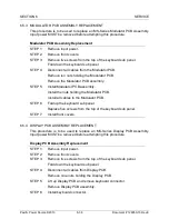
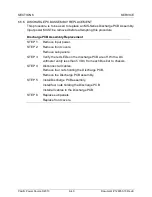
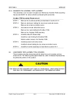
6.5.8 SNUBBER PCB ASSEMBLY REPLACEMENT
This procedure is to be used to replace an MS-Series Snubber PCB Assembly.
Input power MUST be removed before attempting this procedure.
Snubber PCB Assembly Replacement
STEP 1:
Remove the Inverter assembly as described in section 6.5.1.
STEP 2:
Remove all screws holding the top screen and side covers.
Remove top screen and side covers.
STEP 3:
Un-solder and mark all resistor wires.
Remove four nuts holding the Snubber PCB.
Remove the Snubber PCB assembly.
STEP 4:
Install Snubber PCB assembly.
Install four nuts holding the Snubber PCB.
Solder resistor wires to the Snubber PCB.
STEP 5:
Install top screen and side covers.
Install all screws holding the top screen and side covers.
STEP 6:
Install the Inverter assembly as described in section 6.5.1.
6.6
COMPONENT REPLACEMENT PROCEDURES
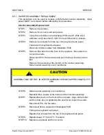
This procedure provides procedures which allow the user to replace various
components. The following paragraphs detail the order of disassembly/assembly
for particular portions of the system.
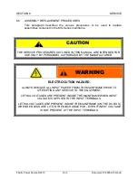
CAUTION
-
THE SERVICE PROCEDURES OUTLINED IN THIS MANUAL ARE INTENDED FOR
USE ONLY BY PERSONNEL AUTHORIZED BY THE MANUFACTURER.
!
Содержание MS SERIES
Страница 1: ...MS SERIES AC POWER SOURCE OPERATIONS MANUAL PACIFIC POWER SOURCE ...
Страница 4: ...THIS PAGE INTENTIONALLY BLANK ...
Страница 19: ...SECTION 2 SPECIFICATIONS Pacific Power Source 2013 2 4 Document 126050 10 Rev E FIGURE 2 2 OUTLINE DRAWING ...
Страница 65: ...SECTION 4 OPERATION Pacific Power Source 2013 4 25 Document 126050 10 Rev E FIGURE 4 5 CABINET ASSEMBLY ...
Страница 84: ...SECTION 6 SERVICE Pacific Power Source 2013 6 3 Document 126050 10 Rev E FIGURE 6 1 1 MAINFRAME ...
Страница 86: ...SECTION 6 SERVICE Pacific Power Source 2013 6 5 Document 126050 10 Rev E FIGURE 6 1 2 CONTROL MODULE ...
Страница 103: ...SECTION 6 SERVICE Pacific Power Source 2013 6 22 Document 126050 10 Rev E FIGURE 6 3 1 PERFORMANCE CHECK FLOW CHART ...
Страница 106: ...SECTION 6 SERVICE Pacific Power Source 2013 6 25 Document 126050 10 Rev E FIGURE 6 3 3 DISPLAY FLOW CHART ...
Страница 108: ...SECTION 6 SERVICE Pacific Power Source 2013 6 27 Document 126050 10 Rev E FIGURE 6 3 4 EMER OFF FLOW CHART ...
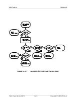
Страница 110: ...SECTION 6 SERVICE Pacific Power Source 2013 6 29 Document 126050 10 Rev E FIGURE 6 3 5 NO INVERTER VOLTAGE FLOW CHART ...
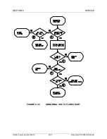
Страница 112: ...SECTION 6 SERVICE Pacific Power Source 2013 6 31 Document 126050 10 Rev E FIGURE 6 3 6 ABNORMAL VOLTS FLOW CHART ...
Страница 114: ...SECTION 6 SERVICE Pacific Power Source 2013 6 33 Document 126050 10 Rev E FIGURE 6 4 2 INPUT POWER SCHEMATIC ...
Страница 115: ...SECTION 6 SERVICE Pacific Power Source 2013 6 34 Document 126050 10 Rev E FIGURE 6 4 3 DC POWER SUPPLY SCHEMATIC ...
Страница 130: ...APPENDIX B SYSTEM SCHEMATIC Pacific Power Source 2013 B 1 Document 126050 10 Rev E FIGURE B 1 3060 MS SYSTEM SCHEMATIC ...

