SECTION 3
INSTALLATION
Pacific Power Source ©2013
3-1
Document # 126050-10 Rev E
3.0 INSTALLATION
WARNING
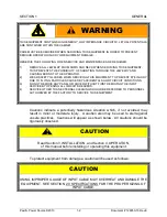
THE PROPER INSTALLATION OF AN MS-SERIES AC POWER SOURCE REQUIRES
A THOROUGH UNDERSTANDING OF THE INFORMATION PRESENTED IN THIS
SECTION OF THE MANUAL.
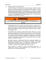
IF THIS EQUIPMENT IS NOT INSTALLED AND USED IN A MANNER SPECIFIED BY
THE MANUFACTURER, THE PROTECTION PROVIDED BY THE EQUIPMENT MAY
BE IMPAIRED
Should any question arise regarding the installation of this equipment, the user is
encouraged to call Pacific Power Source, toll free in the USA at 1-800-854-2433 or 949-
251-1800 internationally.
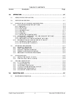
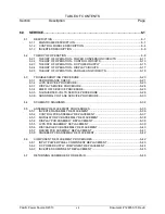
Installation of an MS Power Source consists of the following steps:
1.
Planning the job.
(Refer to paragraph 3.1)
2.
Uncrating and Moving the system.
(Refer to paragraph 3.2)
3.
Changing Input Voltage, if required.
(Refer to paragraph 3.3)
4.
Setting the cabinet into place.
(Refer to paragraph 3.4)
5.
Making Input Connections.
(Refer to paragraph 3.6)
6.
Making Output Connections.
(Refer to paragraph 3.7)
7.
Multiple Cabinet Paralleled Systems.
(Refer to paragraph 3.8)
8.
Inspecting the Installation.
(Refer to paragraph 3.9)
3.1
PLANNING THE JOB
The main objective in planning the job is to determine the hardware required to
install the MS-Series Power Source. Proper consideration of the items below will
allow the installation to proceed in an orderly manner.
The first step in planning the job is to determine the size of power source
required to service the load. In normal situations the load should not exceed
80% of the power source's full load ratings. This margin allows the user to add
future loads to the Power Source without sacrificing surge and overload
capabilities.
Содержание MS SERIES
Страница 1: ...MS SERIES AC POWER SOURCE OPERATIONS MANUAL PACIFIC POWER SOURCE ...
Страница 4: ...THIS PAGE INTENTIONALLY BLANK ...
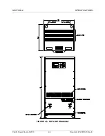
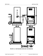
Страница 19: ...SECTION 2 SPECIFICATIONS Pacific Power Source 2013 2 4 Document 126050 10 Rev E FIGURE 2 2 OUTLINE DRAWING ...
Страница 65: ...SECTION 4 OPERATION Pacific Power Source 2013 4 25 Document 126050 10 Rev E FIGURE 4 5 CABINET ASSEMBLY ...
Страница 84: ...SECTION 6 SERVICE Pacific Power Source 2013 6 3 Document 126050 10 Rev E FIGURE 6 1 1 MAINFRAME ...
Страница 86: ...SECTION 6 SERVICE Pacific Power Source 2013 6 5 Document 126050 10 Rev E FIGURE 6 1 2 CONTROL MODULE ...
Страница 103: ...SECTION 6 SERVICE Pacific Power Source 2013 6 22 Document 126050 10 Rev E FIGURE 6 3 1 PERFORMANCE CHECK FLOW CHART ...
Страница 106: ...SECTION 6 SERVICE Pacific Power Source 2013 6 25 Document 126050 10 Rev E FIGURE 6 3 3 DISPLAY FLOW CHART ...
Страница 108: ...SECTION 6 SERVICE Pacific Power Source 2013 6 27 Document 126050 10 Rev E FIGURE 6 3 4 EMER OFF FLOW CHART ...
Страница 110: ...SECTION 6 SERVICE Pacific Power Source 2013 6 29 Document 126050 10 Rev E FIGURE 6 3 5 NO INVERTER VOLTAGE FLOW CHART ...
Страница 112: ...SECTION 6 SERVICE Pacific Power Source 2013 6 31 Document 126050 10 Rev E FIGURE 6 3 6 ABNORMAL VOLTS FLOW CHART ...
Страница 114: ...SECTION 6 SERVICE Pacific Power Source 2013 6 33 Document 126050 10 Rev E FIGURE 6 4 2 INPUT POWER SCHEMATIC ...
Страница 115: ...SECTION 6 SERVICE Pacific Power Source 2013 6 34 Document 126050 10 Rev E FIGURE 6 4 3 DC POWER SUPPLY SCHEMATIC ...
Страница 130: ...APPENDIX B SYSTEM SCHEMATIC Pacific Power Source 2013 B 1 Document 126050 10 Rev E FIGURE B 1 3060 MS SYSTEM SCHEMATIC ...

