Simple Example of Use
Section
4-1
148
Step 4
Downloading the Function Block Data to the Loop Control Unit
1, 2, 3…
1. Turn power OFF to the PC.
2. Set the DIP switches on the front panel of the CPU Unit (SW4: ON when
using the peripheral port, OFF when using the RS-232C port).
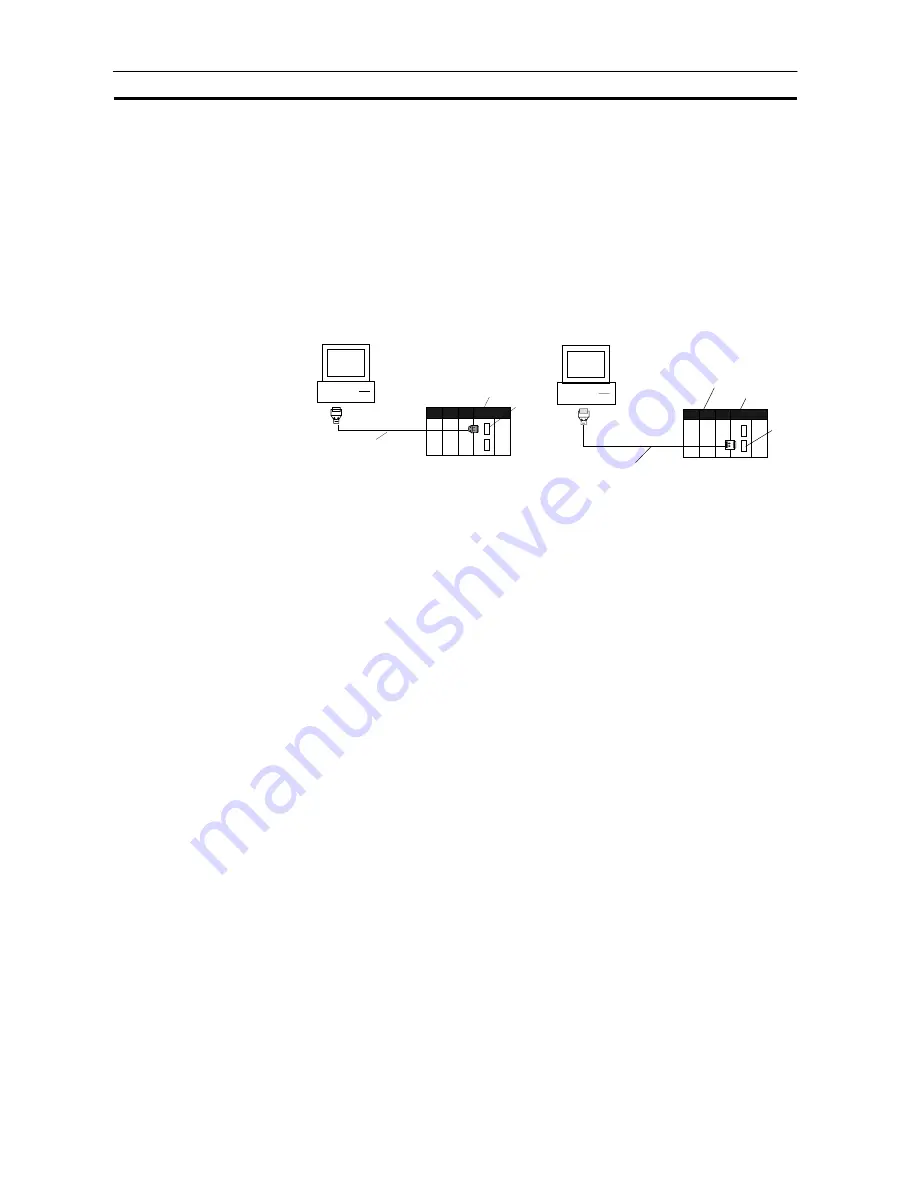
3. Connect the CPU Unit to the Computer on which CX-Process Tool is
running.
Connection to peripheral port
(only Host Link connection is
supported)
Connection to RS-232C port (only
Host Link connection is supported)
Peripheral port
DOS/V PC
(9-pin male)
CS1 CPU Unit
Connector cable CS1W-CN226/626
RS-232C port
DOS/V PC
(9-pin male)
CS1 CPU Unit
Recommended cable XW2Z-200S-V
Loop Control Unit
4. Turn power ON to the PC.
5. Set the network address (000), node address (01) and unit address (unit
10 Hex in decimal) on CX-Process Tool. ([Settings]-[Network
Settings])
6. Establish the Host Link connection on CX-Process Tool. ([File]-[Initialize
Serial Port/F])
7. Download the function block data prepared on CX-Process Tool to the
Loop Control Unit. ([Execution]-[Download])
8. Execute the run/stop command on CX-Process Tool ([Execute]-[Run]-
[Run/Stop Command]) or turn the PC OFF then back ON again.
Note Check the following points before you start Loop Control Unit
operation.
1) The correct combination of Analog Input/Output Units must be
mounted.
2) The unit address set on the front panel of Analog Input/Output
Units must match the unit number set on the Field Terminals.
Otherwise, data input/output (read/write) operations will be
performed by mistake on the data of another Special I/O Unit
(having the unit number set on the Field Terminals).
3) The correct defaults of the System Common block on the Loop
Control Unit must be set. In particular, make sure that the same
applications as those for other PCs are not set for the Data
Memory (DM) for the Node Terminals on the CPU Unit to be
used by the Loop Control Unit.
9. Check the LEDs on the front panel of the Loop Control Unit (RUN LED lit,
ERC LED out).


