


Data Connectors
Serial I/O
This is a DB9-M for factory maintenance; it is not used in normal VOLT operation.
GPI
This is a DB9-F for remote control input, using contact closures or other logic-level systems.
Pin 1
+5VDC Out
Pin 2
Input
Pin 3-6
Trigger input #1 - #4
Pin 7,8,9
GND
The action for each input is controlled by the
GPIO/Events
tab in the Remote Control.
If using pushbuttons or relays, each GPI activates by momentarily connecting its Trigger input
to Ground, while pin 1 is tied to pin 2. (For noise immunity, you may wish to pull the input line
“normal high” by connecting it to the +5V supply through a 1k
Ω
resistor.)
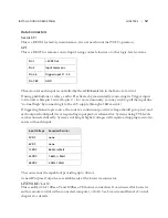
If triggering from a logic source, the source’s continuous positive voltage should go to pin 2, and
each output should pull its corresponding input pin low when active. Systems using TTL levels
can be connected directly. Systems working at higher voltages will require a dropping resistor in
series with each input:
Input Voltage
Required Resistor
5 VDC
none
6 VDC
none
12 VDC
680Ω, ¼ Watt
24 VDC
1.8kΩ, ½ Watt
48 VDC
3.9kΩ, 1 Watt
The source must be capable of providing up to 40 mA.
General Purpose Outputs are available only at the Livewire connector.
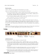
LIVEWIRE / LAN
This is an RJ-45 for 10Base-T and 100Base-T Ethernet connection. It can be used for Livewire
audio, remote control with a connected computer, or both. See Livewire and Remote Control
chapters for details.
CHAPTER 3 |
12
INSTALLATION AND REAR PANEL
Содержание Volt
Страница 40: ...CHAPTER 6 32 VOLT PROCESSING...