DISASSEMBLING PROCEDURE CLV-160
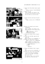
(7) Remove the W-lens holder from the optical
base.
Phillips screwdriver No.2(CCUK3x6SZ)
(8) Remove the lens.
(When assembling, pay attention to the
lens direction. See the drawing on the left.
The lens shall have no dust and stain.)
(9) Remove the limit switch from the optical
base.
Phillips screwdriver No.2 (CCUK3x6SZ)
(10) Remove the terminal from the chassis.
(CCUK3x4SZ)
(When assembling, pay attention to the
terminal direction. See the drawing below.)
c h a s s i s
(11) Remove the electrode F from the optical
base.
(12) Remove the sink holder spring from the
optical base.
Phillips screwdriver No.2 (CCUK3x4SZ x 2)
(13) Remove the cable from the electrode R.
Phillips screwdriver No.2 (CCUK3x4SZ)
(When assembling, pay attention to the
terminal direction. See the drawing below.)
Electrode R
(14) Remove the electrode R from the optical
base.
Phillips screwdriver No.2 (CCUK3x6SZ x 3)
(15) Remove the screws in the order specified
on the left, and remove the discharge
spring, the cord stopper, the discharge
plate and the cable.
(The discharge spring and the discharge
plate shall have no dust and stain.)
5-7
Содержание CLV-160
Страница 1: ...MAINTENANCE MANUAL CLV 160...
Страница 8: ...2 C O N N E C T I O N D I A G R A M 2 1...
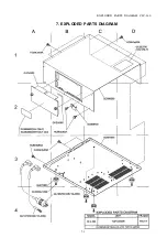
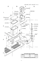
Страница 45: ...EXPLODED PARTS DIAGRAM CLV 160 7 EXPLODED PARTS DIAGRAM 7 1...
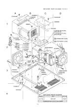
Страница 46: ...EXPLODED PARTS DIAGRAM CLV 160 7 2...
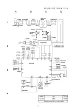
Страница 47: ...EXPLODED PARTS DIAGRAM CLV 160 7 3...
Страница 48: ...EXPLODED PARTS DIAGRAM CLV 160 7 4...
Страница 49: ...EXPLODED PARTS DIAGRAM CLV 160 7 5...
Страница 50: ...EXPLODED PARTS DIAGRAM CLV 160 7 6...
Страница 51: ...EXPLODED PARTS DIAGRAM CLV 160 7 7...

