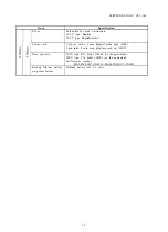
SPECIFICATIONS CLV-160
Item
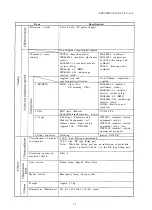
Air supply pump
Air supply pressure
Specification
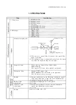
Diaphragm system
(1) Adjustable in 3 steps (strong/medium/weak and stop)
(2) Maximum pressure less than 53.9kPa
Control
Setting of the air supply switch
Method
Supply from the scope end by combining the scope with the
supply water tank.
Scope
One touch connection
Light control cable:MH-966
Light control cable:MAJ-586
Emergency lamp
Connector on the rear panel
(Light control cable for CV)
Connector on the rear panel
(Light control cable for OTV)
When the emergency lamp breaks (including connection
failure), LED flickers to warn to replace the lamp. When the
emergency lamp is lit, LED is lit.
Storage of set values
The setting is stored before the power switch is turned off and
when the power switch is turned off.
Setting of manual/auto light adjustment
Setting of air supply pressure
Light intensity control level
On removal of the scope
When the scope is removed, the emergent light from the scope
output connector is dimmed with the diaphragm blade to the
minimum diaphragm position.
P a n e l
Disinfect with ethanol for disinfection (70% ethyl or isopropyl
alcohol) or sterilized water.
Temperature switch
When the temperature in the system rises over the rated
maximum value, the temperature switch automatically turns
off and the current is shut off to ensure safety. The function of
the temperature switch is detected and warned by an audible
tone.
l-2
Содержание CLV-160
Страница 1: ...MAINTENANCE MANUAL CLV 160...
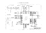
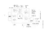
Страница 8: ...2 C O N N E C T I O N D I A G R A M 2 1...
Страница 45: ...EXPLODED PARTS DIAGRAM CLV 160 7 EXPLODED PARTS DIAGRAM 7 1...
Страница 46: ...EXPLODED PARTS DIAGRAM CLV 160 7 2...
Страница 47: ...EXPLODED PARTS DIAGRAM CLV 160 7 3...
Страница 48: ...EXPLODED PARTS DIAGRAM CLV 160 7 4...
Страница 49: ...EXPLODED PARTS DIAGRAM CLV 160 7 5...
Страница 50: ...EXPLODED PARTS DIAGRAM CLV 160 7 6...
Страница 51: ...EXPLODED PARTS DIAGRAM CLV 160 7 7...


