DISASSEMBLING PROCEDURE CLV-160
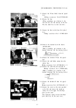
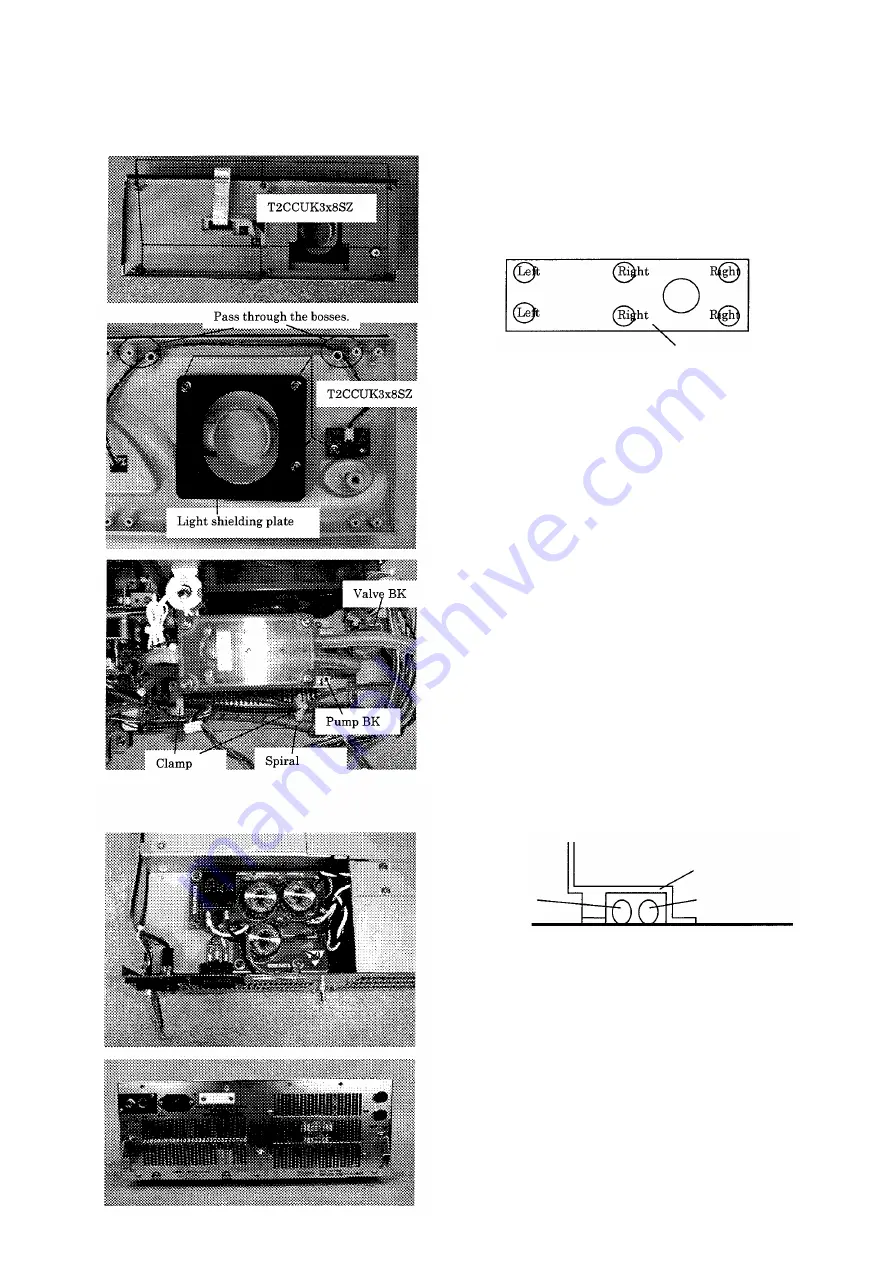
(5) Remove the FP chassis from the panel.
Phillips screwdriver No.2 (T2CCUK3x6SZ x 6)
(When assembling, pay attention to the
tightening hole positions. See the drawing
below. The idle hole is spare.)
Upper
Lower
FP chassis
(6) Remove the light shielding plate from the
panel.
Phillips screwdriver No.2 (T2CCUK3x8SZ x 3)
(7) Remove the harness from the sheet switch
and LED board.
Phillips screwdriver No.2 (T2CCUK3xWZ)
3. Pump
(1) Remove the scope detection harness and
the diaphragm harness from the clamp.
(2) Remove the harness wound around the
spiral from the pump BK.
Phillips screwdriver No.2 (CCUK3x6SZ x 2)
(3) Remove the spiral from the harness (except
the scope detection harness) from the
socket.
(4) Cut the two binders, and remove the valve
U from the valve BK.
Nippers
(5) Cut the binder, and remove the S-tube
from the valve U.
Nippers
(6) Remove the pump from the chassis.
Box screwdriver(5.5mm)(C6N3SZ x 4)
Pump BK
Suction side
tube
Tube from the
socket
4 . Rear panel
(1) Remove the NF board side of the cable of
the inlet-NF board.
(2) Remove the fuse side of the cable of the
fuse-NF board.
(3) Remove the screws, and remove the rear
panel from the chassis.
Phillips screwdriver No.2 (HCBK3x6SA x 7)
5-3
Содержание CLV-160
Страница 1: ...MAINTENANCE MANUAL CLV 160...
Страница 8: ...2 C O N N E C T I O N D I A G R A M 2 1...
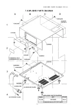
Страница 45: ...EXPLODED PARTS DIAGRAM CLV 160 7 EXPLODED PARTS DIAGRAM 7 1...
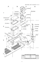
Страница 46: ...EXPLODED PARTS DIAGRAM CLV 160 7 2...
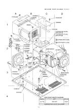
Страница 47: ...EXPLODED PARTS DIAGRAM CLV 160 7 3...
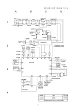
Страница 48: ...EXPLODED PARTS DIAGRAM CLV 160 7 4...
Страница 49: ...EXPLODED PARTS DIAGRAM CLV 160 7 5...
Страница 50: ...EXPLODED PARTS DIAGRAM CLV 160 7 6...
Страница 51: ...EXPLODED PARTS DIAGRAM CLV 160 7 7...


