background image

GB

F

D

32

○○○○○○○○○○○○○○○○○○○

○○○○○○○○○○○○○○○○○○○○○○○○○○○○○○○○○○○○○○○○○○○○○○○○○○○○○○○○○○○○○○○○○○○○○○○○○

○○○○○○○○○○○○○○○○○○○

○○○○○○○○○○○○○○○○○○○○○○○○○○○○○○○○○○○○○○○○○○○○○○○○○○○○○○○○○○○○○○○○○○○○○○○○○

○○○○○○○○○○○○○○○○○○○

○○○○○○○○○○○○○○○○○○○○○○○○○○○○○○○○○○○○○○○○○○○○○○○○○○○○○○○○○○○○○○○○○○○○○○○○○

I

FILTER MAINTENANCE

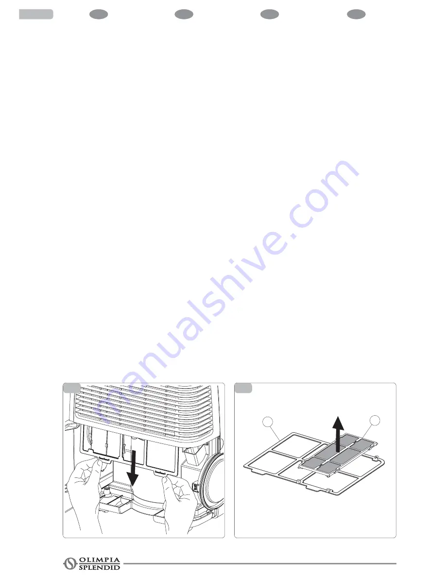
The filtering system is composed
of a mesh filter (fig. 13 ref. A) and a
removable frame (fig. 13 ref. B) onto
which the additional filters can be
positioned.

To dismount the filtering system:
• Press the condensation collection

tank door (fig. 6).

• Once the door is unhooked, open

it by pulling outwards (fig. 7).

• Extract the tank of the device by

grasping it from the lower and
upper part simultaneously as
illustrated in the figure (fig. 8).

• Flex the air filter by pressing the

lower tabs in order to release the
hooks.

• Keep the two tabs pressed and

withdraw the filtering system from
the machine pulling the tabs
downwards (fig. 12).

The filtering system withholds any
impurities present in the air, for this
reason it should be cleaned every
month.
Use running water to clean the mesh
filter (fig. 13 ref. A). Any additional
filters should be replaced after
approx. 500 hours of use. For
correct functioning of the filtering
system it is recommended to use
only original OLIMPIA SPLENDID
spare parts.

To remount the filtration system:
• Insert the filtering system into the

appropriate seat of the machine
and simultaneously press the
lower tabs in order to insert it into
the hooks of the air inlet grill.

• Reposition the tank in the

appropriate compartment .

• Close the door.

3

3.6

13

12

MANUTENZIONE FILTRI

Il sistema filtrante è composta da
un filtro a rete (fig. 13 rif. A) e da un
telaietto smontabile (fig. 13 rif. B)
su cui possono essere inseriti i filtri
addizionali.

Per smontare il sistema filtrante:
• Premere il portello tanica raccolta

condensa (fig. 6)

• Una volta sganciato il

portello,aprirlo ruotandolo verso
l'esterno (fig. 7)

• Estrarre la tanica dall'apparecchio

afferrandola contemporaneamen-
te dalla parte inferiore e superiore
come illustrato in figura (fig. 8)

• Flettere il filtro dell'aria premendo

le linguette inferiori in modo da
liberarlo dai ganci.

• Tenere premute le due linguette e

sfilare il sistema filtrante dalla
macchina tirando le linguette ver-
so il basso (fig. 12).

Il sistema filtrante trattiene le impu-
rità presenti nell’aria, per questo
motivo si consiglia di eseguire men-
silmente la pulizia.
Per pulire il filtro a rete (fig. 13 rif.
A) usare acqua corrente, per i filtri
addizionali è necessario procedere
alla sostituzione dopo circa 500 ore
di utilizzo. Per un corretto funziona-
mento del sistema filtrante si con-
siglia di utilizzare unicamente ricam-
bi originali OLIMPIA SPLENDID.

Per rimontare il sistema filtrante:
• Infilare il sistema filtrante nella

apposita sede nella macchina e
contemporaneamente premere le
linguette inferiori in modo da infi-
larlo nei ganci della griglia entrata
aria.

• Ricollocare la tanica nel proprio

vano

• Richiudere il portello.

B

A

ENTRETIEN DES FILTRES

Le système filtrant se compose d'un
filtre à treillis (fig. 13 rif. A) et d'un
petit châssis démontable (fig. 13 réf.
B) sur lequel il est possible d'installer
des filtres supplémentaires.

Pour démonter le système filtrant:
• Appuyer sur le portillon du bidon

de récupération des condensats
(fig. 6)

• Une fois le portillon débloqué,

l'ouvrir en le tournant vers
l'extérieur (fig. 7).

• Enlever le bidon de l'appareil en le

saisissant simultanément par la
partie inférieure et supérieure de
la façon illustrée dans la figure
(fig. 8).

• Infléchir le filtre à air en appuyant

sur les languettes inférieures de
façon à le libérer des crochets.

• Maintenir les deux languettes

enfoncées et ôter le système
filtrant de la machine en tirant les
languettes vers le bas (fig. 12).

Le système filtrant retient les
impuretés présentes dans l'air,
aussi est-il est conseillé de
procéder mensuellement au
nettoyage. Pour nettoyer le filtre à
treillis (fig. 13 réf. A) utiliser de l'eau
courante, pour les filtres
additionnels il est nécessaire de
procéder au remplacement au bout
d'environ 500 heures d'utilisation.
Pour assurer un bon fonctionnement
du système filtrant, il est conseillé
d'utiliser uniquement des pièces de
rechange originales OLIMPIA
SPLENDID.

Pour remonter le système filtrant :
• Insérer le système filtrant dans le

logement prévu à cet effet sur la
machine et, simultanément,
appuyer sur les languettes
inférieures de façon à l'insérer
dans les crochets de la grille
d'entrée de l'air.

• Remettre le bidon en place dans

son logement

• Refermer le portillon

WARTUNG DER FILTER

Das Filtriersystem besteht aus einem
Netzfilter (Abb. 13 Pos. A) und einem
abmontierbaren Rahmen (Abb. 13
Pos. B), auf dem die Zusatzfilter
eingesetzt werden können.

Zum Ausbau des Filtriersystems:
• Drücken Sie die Klappe des

Kondenswassersammelbehälters
(Abb. 6)

• Öffnen Sie die Klappe nach dem

Aushängen, indem Sie sie nach
außen drehen (Abb. 7)

• Ziehen Sie den Behälter vom

Gerät, indem Sie diesen
gleichzeitig vom unteren und
oberen Teil ergreifen, siehe
Abbildung (Abb. 8)

• Biegen Sie den Luftfilter, indem

Sie die unteren Laschen drücken,
sodass der Filter von den Haken
gelöst wird.

• Halten Sie die beiden Laschen

gedrückt und ziehen Sie das
Filtriersystem von der Maschine,
indem Sie die Laschen nach unten
ziehen (Abb. 12).

Das Filtriersystem hält die in der
Luft vorhandenen Verunreinigungen
zurück. Es empfiehlt sich daher
seine monatliche Reinigung.
Verwenden Sie zur Reinigung des
Netzfilters (Abb. 13 Pos. A)
fließendes Wasser. Für die
Zusatzfilter ist die Auswechselung
nach zirka 500 Betriebsstunden
erforderlich. Zur Gewährleistung des
Filtriersystems sollten nur
Originalersatzteile von OLIMPIA
SPLENDID verwendet werden.

Zum Wiedereinbau des
Filtriersystems:
• Führen Sie das Filtersystem in den

vorgesehenen Sitz in der Maschine
ein und drücken Sie gleichzeitig
derart die unteren Laschen, dass
es sich in die Haken des
Lufteingangsfilters fügt.

• Stellen Sie den Behälter wieder in

seinen Schacht.

• Schließen Sie die Klappe.

Содержание Aquaria

Страница 1: ...STALLATION USE AND MAINTENANCE INSTRUCTIONS POUR L INSTALLATION L EMPLOI ET L ENTRETIEN HANDBUCH F R INSTALLATION GEBRAUCH UND WARTUNG INSTRUCCIONES PARA LA INSTALACI N USO Y MANTENIMIENTO MANUAL DE I...

Страница 2: ...TENANCE 3 9 CLEANING THE DEHUMIDIFIER 3 10 STORING THE DEHUMIDIFIER ELECTRICAL DIAGRAM SPECIFICATIONS TROUBLE SHOOTING SOMMAIRE 1 GENERALITES 1 1 INFORMATIONS GENERALES 1 2 SYMBOLOGIE 1 2 1 Pictogramm...

Страница 3: ...3 2 1 Stand by 3 2 2 Selec o da modalidade de funcionamento AQUARIA 3 2 3 Selec o da modalidade de funcionamento AQUARIA THERMO 3 2 4 Visualiza o da temperatura e da humidade do ambiente 3 3 FUNCIONAM...

Страница 4: ...nt r serv aux termes de la loi avec interdiction de reproduction ou de transmission tiers sans l autorisation expresse de le fabricant Lireattentivementlepr sentmanuel avantdeproc der touteop ration i...

Страница 5: ...evem serdelxadosaoalcancedascrin as pois s opotenciaisfontesdeperigo AFIRMACONSTRUTORAN OSEAS SUMEARESPONSABILIDADEPOR DANOSAPESSOASOUACOISAS PROVOCADOS PELA INOBSERV NCIA DAS NORMAS CONTIDASNOPRESENT...

Страница 6: ...et de mani re univoque les informations n cessaires pour uneutilisationcorrectedelamachine dans des conditions de s curit Pictogrammes r dactionnels Service Indique des situations o il faut informer...

Страница 7: ...ictogramas relativos seguran a Tens oel tricaperigosa Avisa o pessoal interessado que a opera o descrita apresenta se n o for efectuada respeitando as normativas de seguran a o risco de sofrer um choq...

Страница 8: ...densation discharge hose 2 Hose collar clamp 3 3 x additional filters 4 Use Maintenance Manual guarantee Communiquercesinstructions tout lepersonnelconcern parletransport et l installation de la machi...

Страница 9: ...tos v lidoparaos Estados membrosdaUE IDENTIFICA O DAS PARTES PRINCIPAIS fig 1 1 Paineldecomandos 2 Filtro de ar 3 Tanquederecolhada condensa o 4 Puxadordedesloca o 5 Grelha de sa da do ar 6 Portinhola...

Страница 10: ...mage to property caused by inappropriate incorrect or unreasonableuse 1 6 DESCRIPTION DU FONCTIONNEMENT L air humide aspir par le ventilateur traverse un serpentin r frig rant qui provoque la condensa...

Страница 11: ...gsstanden kiezen ZUIVEREN ONTVOCHTIGEN AUTOMATISCH ONTVOCHTIGEN ONTVOCHTIGEN VERWARMEN BELANGRIJKEAANWIJZINGEN Om beschadigingen van de compressortevoorkomenwordt dezelaatstemeteenvertragingvan 3 minu...

Страница 12: ...sphere R 134A is a fluorinated greenhouse gas covered by Kyoto Protocol with a Global Warming Potential GWP 1300 En cas de panne et ou de mauvais fonctionnement de l appareil l teindre et ne pas tente...

Страница 13: ...n vertrekken waar de lucht gas olie of zwavel kan bevatten en ook niet in de buurt van warmtebronnen Leg geen zware of hete voorwerpen bovenop het apparaat Als u besluit om het apparaat af te danken w...

Страница 14: ...ment travers une prise compatible avec la fiche fournie INSTALLATION Das Ger t in einem zweckentsprechenden Raum aufstellen Frontseitig des Luftsauggitters ist ein Freiraum von mindestens 50 cm zu las...

Страница 15: ...voedingskabel met stekker aansluiting van het type Y Controleer alvorens de klimaatregelaar aan te sluiten of De waarden van de voedingsspanning en frequentie overeenstemmen met de specificaties op h...

Страница 16: ...placement ventuel du cordon d alimentation doit tre effectu exclusivement par le service technique Olimpia Splendid ou par du personnel ayant une qualification similaire AVERTISSEMENT Il faut pr voir...

Страница 17: ...de tipo 5AT para o modelo AQUARIA e 10 AT para o modelo AQUARIA THERMO ou outros dispositivos com fun es equivalentes ADVERT NCIA Aliga o rededealimenta odeve ser efectuada pelo instalador exceptoosa...

Страница 18: ...tivate the appliance press the key A MODE D EMPLOI ET ENTRETIEN TABLEAU DE COMMANDE Le d shumidificateur que vous avez achet est quip d une logique lectronique qui g re son fonctionnement de mani re o...

Страница 19: ...lering gemeten vochtigheidsgraad omgevingstemperatuur F Aanduiding temperatuur G Aanduiding vochtigheidsgraad H Ontvochtigen I Aanduiding condensopvangbak vol afwezig L Verwarmingsmodaliteit alleen TH...

Страница 20: ...igure 4 the current degree of humidity is visualised The appliance works continuously cleaning the air S lection mode de fonctionnement AQUARIA La touche B figure 4 permet la s lection entre deux mode...

Страница 21: ...iminuir em passos de 5 o valor desejado de humidade do ambiente O aparelho funciona at alcan ar o valor desejado depois desliga se automaticamente Assim que a humidade relativa do ambiente ultrapassa...

Страница 22: ...l as dehumidifying It is advisable to set a desired humidity value between 40 and 60 D SHUMIDIFICATION L activation de cette fonction est indiqu e par le symbole goutte allum l cran Il est possible de...

Страница 23: ...modo autom tico eligiendo el valor de humedad m s confortable en base a la temperatura ambiente DESHUMIDIFICACI N CALEFACCI N La activaci n de esta funci n se indica mediante los s mbolos gota y sol...

Страница 24: ...da diese Alarm meldung auch bei einem h heren F e u c h t i g k e i t s g r a d eingeblendet bleibt ist ein Service Zentrum zu Hilfe zu ziehen Affichage de la temp rature et de l humidit ambiante D a...

Страница 25: ...el display los valores de temperatura y humedad ambiente detectados por el aparato ADVERTENCIA Cuando la humedad relati va desciende a valores muy bajos 20 25 o bien que no justifiquen el funcionamien...

Страница 26: ...d in the figure fig 8 Extract the condensation discharge plug from the door fig 9 FUNZIONAMENTO CON SCARICO CONTINUO Per fare funzionare il deumidificato re in scarico continuo eseguire le seguenti op...

Страница 27: ...la puerta del bid n colector de condensaci n para permitir su apertura Fig 6 Una vez desenganchada la puerta brala gir ndola hacia fuera Fig 7 Extraiga el bid n del aparato tom ndolo simult neamente...

Страница 28: ...ING The continuous discharge function is cancelled when reinserting the empty tank Collegare il tubo di gomma al raccordo della vaschetta raccol ta condensa nella parte superio re del vano tanica fig...

Страница 29: ...al racor con la abrazadera met lica Cierre la puerta haciendo pasar el tubo de goma a trav s del paso previsto Fig 11 Con la m quina en la funci n presionar simult neamente por tres segundos las tecl...

Страница 30: ...dans le bidon Remettre le bidon en place dans son logement Refermer le portillon ATTENTION eau non potable n tant pas indiqu e un usage alimentaire LOW TEMPERATURE OPERATION The dehumidifier is able...

Страница 31: ...chine enkele minuten lang een geluidssignaal laten horen De ontvochtiger gaat uit en om er de werking van te herstellen moet u de volgende handelingen uitvoeren Druk n keer op het deurtje van de jerry...

Страница 32: ...filtrant se compose d un filtre treillis fig 13 rif A et d un petit ch ssis d montable fig 13 r f B sur lequel il est possible d installer des filtres suppl mentaires Pour d monter le syst me filtrant...

Страница 33: ...Mantenga presionadas las dos leng etas y extraiga el sistema filtrante de la m quina tirando de las leng etas hacia abajo Fig 12 El sistema filtrante retiene las impurezas presentes en el aire por es...

Страница 34: ...r from penetrating inside Do not use a direct water jet since this could affect the safety of the device STORING THE DEHUMIDIFIER Disconnect the plug Clean the air filter Empty the tank of condensatio...

Страница 35: ...aintervenci n REGELMATIG ONDERHOUD Voordat u welke onderhoud swerkzaamheden dan ook uitvoert moet u altijd eerst de stekker uit het stopcontact halen SCHOONMAKEN VAN DE ONTVOCHTIGER Alvorens met het s...

Страница 36: ...allumage veille S305 Touche de s lection du mode de fonctionnement T1 Transformateur SCHEMA ELETTRICO A1 Scheda elettronica potenza A2 Scheda sensore umidit temperatura A3 Scheda elettronica comando...

Страница 37: ...ventilator RY101 Relais verwarmingsweerstand alleen versie THERMO M1 Motorcompressor M2 Ventilator S1 Microschakelaar tank vol afwezig S301 Toets signalering vochtigheid temperatuur omgeving gemeten S...

Страница 38: ...druck Entfeuchtungskapazit t I GB F D DATI TECNICI Per i dati tecnici sotto elencati consultare la targa dati caratteristi ca applicata sul pro dotto Tensione di alimentazione Potenza assorbita massim...

Страница 39: ...e raadplegen Voedingsspanning Maximaal geabsorbeerd vermogen Maximaal geabsorbeerde stroom Koelgas Beschermklasse van de ombouw Max bedrijfsdruk Ontvochtigingscapaciteit Potencia elemento calefactor M...

Страница 40: ...on temperature sensor is damaged The ambient temperature is too low INDIVIDUAZIONE DI ANOMALIE DI FUNZIONAMENTO CAUSE Spina non collegata L umidostato regolato sul minimo La tanica piena d acqua Le te...

Страница 41: ...t du local Le code alarme Hr clignotant s affiche l cran Le code alarme tE clignotant s affiche l cran Le code alarme Lo clignotant s affiche l cran KLEINE ST RUNGEN SELBST BEHEBEN ST RUNGEN Der Entfe...

Страница 42: ...y aparece el c digo alarma Hr titilante En el display aparece el c digo alarma tE titilante En el display aparece el c digo alarma Lo titilante DETEC O DE ANOMALIAS DE FUNCIONAMENTO CAUSAS A ficha est...

Страница 43: ...n met kokend water e d in de ruimte De omgevingsvochtigheidsgraad is te laag De sensor voor de temperatuur en vochtigheidsgraad van de ruimte is beschadigd De sensor voor de verdampingstemperatuur van...

Страница 44: ...GB F D 44 I...

Отзывы: