


40496501TH Draft Version
72
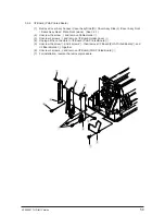
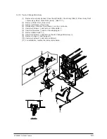
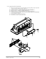
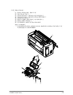
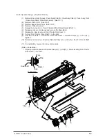
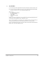
3.3.19 Head Cable
(1)
Remove Cover Assy Access / Cover Assy Side (R) / Cover Assy Side (L) /Cover Assy Front
/ Frame Assy Rear / Plate Front (stuck). (See 3.3.1)
(2)
Remove Printing Head. (See 3.3.18)
(3)
Remove Printer Unit. (See 3.3.2)
(4)
Remove Cable Holder Cover. (See 3.3.6)
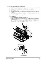
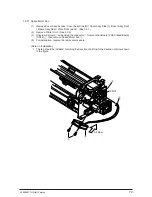
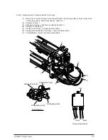
(5)
Unscrew the screw
1
and remove Carriage Cable Holder
2
.
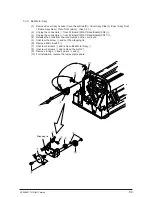
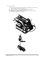
(6)
Unplug Head Connector
3
and then the connector (green)
4
.
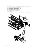
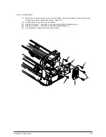
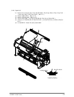
(7)
Unscrew 2 screws
5
and remove Head Cable Cover
6
.
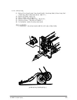
(8)
Unplug Head Cable
7
, pulling it to the left.
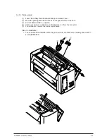
(9)
For installation, reverse the removal procedure.
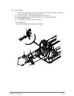
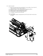
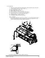
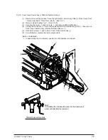
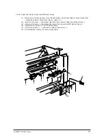
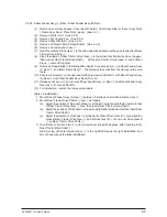
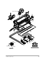
(Note on Installation)
1. When the head cable is assembled, make sure that 0.5 - 1.5mm clearance between cables
should be secured and the amount of protrusion from the side frame (R) should be approx.
10mm on condition that the carriage is dhifted to the left end.
1
2
3
5
6
4
7
0.5 – 1.5
0.5 – 1.5
0.5 – 1.5
0.5 – 1.5
10
Side frame (R)
Head cable
Head cable guide
The condition of cables when the carriage is shifted to the left end
Содержание PACEMARK 4410
Страница 1: ...PACEMARK 4410 PRINTER SERVICE HANDBOOK...
Страница 52: ...40496501TH Draft Version 52 Figure 3 1 3 2 Parts Layout...
Страница 95: ...40496501TH Draft Version 95...
Страница 151: ...40496501TH Draft Version 151 No Yes End Replace PHA Board Recovered No Yes End Replace PMA Board...
Страница 168: ...XXXXXXXXTH Draft Version 8 5 Fig 8 5 45 38 38 40 42 39 44 44 122 41...
Страница 169: ...XXXXXXXXTH Draft Version 8 6 142 141 11 119 Fig 8 6...
Страница 170: ...XXXXXXXXTH Draft Version 8 7 Fig 8 7 105 102 61 33 104 100 101...
Страница 171: ...XXXXXXXXTH Draft Version 8 8 Fig 8 8 55...


