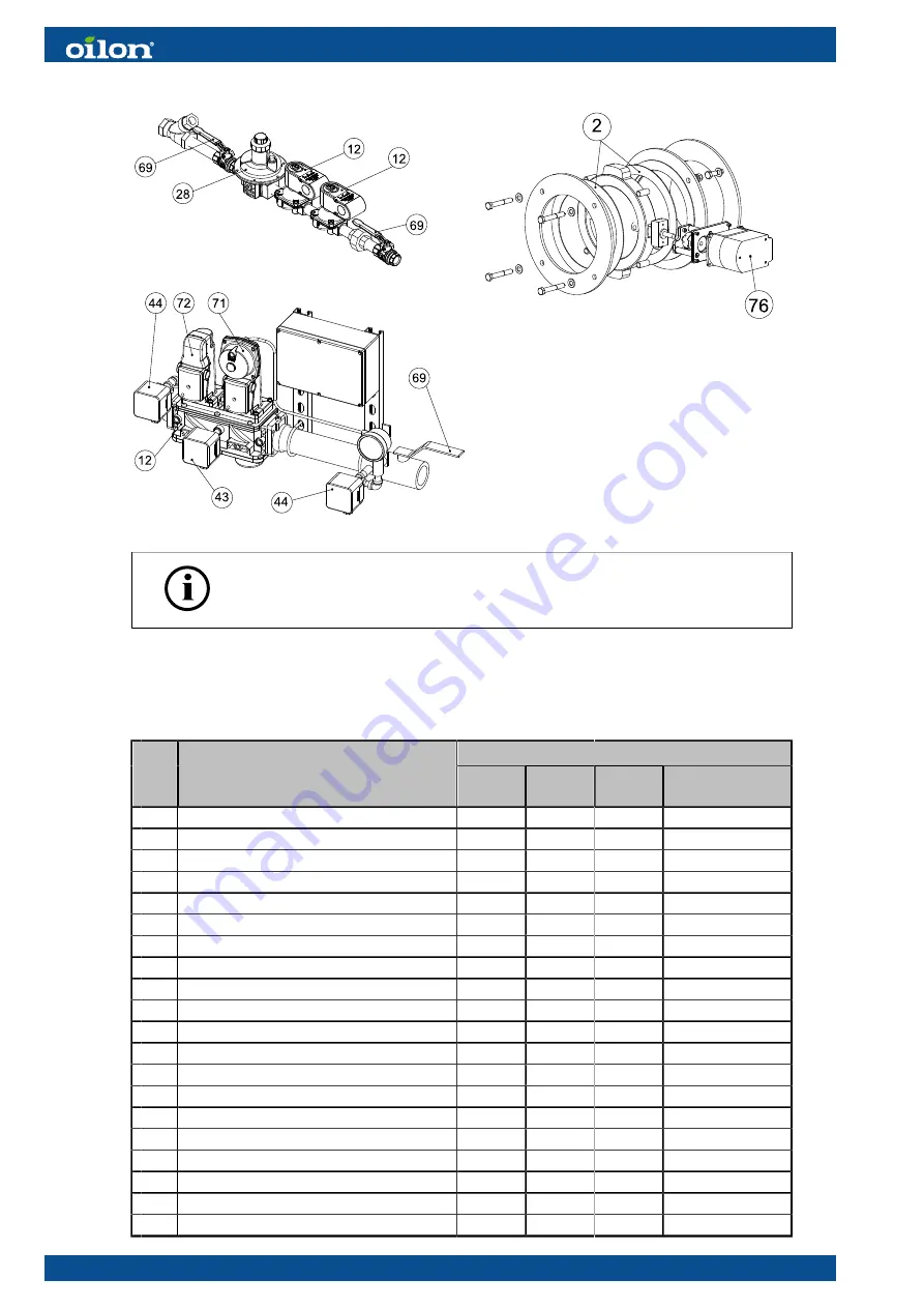
background image

Pilot gas train

Main gas train

FGR

The assembly may vary depending on the scope of delivery.

6.12 Burner part list

Recommended change interval

#

Part name

1–2

year

3–5

years

10

years

on demand/

start-up max.

Protective cover


X

Flange gasket


X

Fan motor


X

Fan wheel


X

Gas nozzle


X

12 

Gas valve block


X

250 000

28 

Pressure regulator


X


32 

Combustion head


X

36 

Ignition transformer


X


37 

Flame detector


     QRI


X


40 

Ignition electrode


X


44 

Pressure switch, gas


X


56 

Differential air pressure switch


X


59 

Servomotor, air


X


60 

Servomotor, gas


X


69 

Manual shut-off valve


X

71 

Valve actuator with pressure regulator


X


72 

Valve actuator


X


76 

Servomotor, FGR


X


110 (111)

M4219 2305EN

Содержание GP-600 M

Страница 1: ...M4219 2305EN 6 April 2023 Operation and maintenance manual Burner models GP 600 M 700 M III Burner equipment WDx00 FGR UL Read these instructions carefully before installation use or maintenance...

Страница 2: ......

Страница 3: ...nstalling burner to gas supply line 23 3 7 Gas valve selection table 25 3 8 Installing gas pressure regulating assembly 25 3 9 Installing FGR duct system 27 3 10 Changing the fuel type from natural ga...

Страница 4: ...combustion air temperature WD200 74 4 31 Activating O2 trim control WD200 75 4 32 Backing up parameters 75 5 Operation 5 1 WiseDrive system 76 5 2 Control panel 79 5 3 Legend to time sequence diagram...

Страница 5: ...Failure to follow these instructions can lead to damage to the appliance Erroneous use of the appliance or the failure to follow any instructions or warnings in the manual or this disclaimer can lead...

Страница 6: ...afety warnings and instructions Connectors in the control box are under voltage Only authorized users may open the safety cover Installation commissioning or service of the appliance is to be carried...

Страница 7: ...ee times do not restart burner before carefully investigating the reason for the failure Do not touch hot pipes or surfaces during operation or maintenance Permissible gas inlet temperature range is 5...

Страница 8: ...ipework and its tightness safety appliances in the boiler system and the burner Check the boiler and its components We recommend obtaining a maintenance contract WARNING IF YOU SMELL GAS 1 OPEN A WIND...

Страница 9: ...housing is finished with durable high gloss paint Electrical installations and burner service are easy to perform because the top cover is removable The stainless steel alloy combustion head and the d...

Страница 10: ...II III Higher value higher capacity Label element 5 Control system additional code WD100 Electronic fuel air ratio control system WD200 Electronic fuel air ratio control system with O2 control and var...

Страница 11: ...e Hz hp A 1 4 Flue gas recirculation optional The flue gas recirculation FGR reduces the NOx content of flue gases A certain proportion of flue gas is led back to the combustion chamber which causes t...

Страница 12: ...h the device also with a second hand product Pass on the documents delivered with device to the owner at installation and advise them to keep them properly Make sure that operating instructions are av...

Страница 13: ...peed rpm 20 0 23 5 3 510 Weight lbs 1014 Burner GP 700 M GP 700 M II GP 700 M III Capacity MMBtu h 4 5 31 8 5 1 36 0 5 7 39 8 Burner motor 3 208 600 V 60 Hz Output hp Current A 460 V Speed rpm 25 31 3...

Страница 14: ...must be known Consult burner manufacturer on the suitability of the burner for special gases Gas inlet pressure to burner max Natural gas 8 200 W C LPG 11 200 W C Max demand for combustion air gas us...

Страница 15: ...nditions 96 VAC Transformer primary side 120 VAC Transformer side 1 12 VAC Transformer side 2 2 x 12 VAC Mains frequency 50 60 Hz 6 Power consumption 30 W Permissible input current differential air pr...

Страница 16: ...Block diagram of contact links Block diagram ver 7 14 111 M4219 2305EN...

Страница 17: ...g time 10 s 120 s 30 s 120 s 60 s 120 s 30s Degree of protection NEMA 3 NEMA 3 NEMA 3 NEMA 4 Permissible ambient temperature 4 140 F 4 140 F 4 140 F 4 140 F 2 5 Display and operating unit technical da...

Страница 18: ...10 VAC 15 10 Power consumption max 90 W typically 45 W controlled Measuring cell temperature 1292 F 122 F Measuring range 0 2 20 9 O2 Flue gas velocity 3 28 32 81 ft s Protection degree NEMA 2 Max tem...

Страница 19: ...ignal amplifier continuous or interrupted use mains frequency filtering does not detect electric arc used for ignition spectral sensitivity range 1 3 m QRI2A2 B180B front viewing QRI2B2 B180B side vie...

Страница 20: ...from all sides with a forklift When lifting the package the center of gravity must be in the middle between the forks to avoid falling B444K ver 3 1 Protective cover 2 Protective cover 3 Lifting stra...

Страница 21: ...y the minimum requirements 3 3 Installing burner Prepare boiler front plate in accordance with the given dimensions Coat bolt threads with graphite bearing grease prior to fitting Install burner so th...

Страница 22: ...700 M III 64 96 15 75 11 61 5 71 47 24 41 73 30 71 16 54 13 19 Burner B1 B2 B3 B4 D1 D2 R1 R2 600 M 17 13 25 39 10 63 21 65 15 55 16 73 56 69 55 12 700 M 19 29 27 56 12 01 21 65 15 55 16 73 58 66 60 6...

Страница 23: ...17 91 4xM20 15 55 12 20 60 90 700 M 18 31 18 31 17 91 4xM20 15 55 12 20 60 90 700 M II 18 31 18 31 17 91 4xM20 15 55 12 20 60 90 700 M III 18 31 18 31 18 90 4xM20 16 73 15 75 60 90 Dimensions in inche...

Страница 24: ...te 3 Slide the first gasket into place over the stud screws 4 Using the strap or chain lift the extension plate Slide the plate onto the stud screws 5 Let the extension plate rest on the stud screws a...

Страница 25: ...nstalling burner to gas supply line Supply line If necessary decrease the supply gas pressure with pressure regulating assembly The gas supply line after the pressure regulator must be of the same siz...

Страница 26: ...re is a separate filter upstream from gas equipment Install the gas valve so that the valve is not subjected to mechanical stress Vent gas piping before first start up Clean and check piping prior to...

Страница 27: ...e PSI Type Size inch 600 700 M III 2 18 7 25 VGD 2 5 6 If the gas inlet pressure is less than 8 in WC or if some other gas except natural gas is used case specific evaluation must be made 3 8 Installi...

Страница 28: ...re is not stable stabilize the pressure with the pressure regulator Example of gas pressure regulating assembly B311Z ver 4 Pos Item Pos Item 1 Gas pressure regulating assembly 9 Bellows compensator g...

Страница 29: ...er constructions pos 2 and 3 are integrated parts of the burner Burner Minimum diameter of FGR pipe 300 M II 300 M III 6 400 M I 600 M 8 700 M 700 M III 10 Designing FGR piping When designing the pipi...

Страница 30: ...s To mount FGR duct system 1 Place the inlet to the stack as close as possible to the boiler or economizer Set cutting in 45 angle 2 Set control damper close to the burner 3 Finish the FGR duct pipe j...

Страница 31: ...d according to the capacity demand Note the quantity of gas flow in relation to function of the compound regulator Check the combustion values with flue gas analysis and if necessary adjust the burner...

Страница 32: ...rdance with local rules and regulations Also note that in certain models the motor output is integrated in the burner wiring base In burners with an external control cabinet the supply for the control...

Страница 33: ...t start up First start up check list Check the following before first start up instructions from boiler and burner manufacturers are followed piping is done properly and joints on pipes and components...

Страница 34: ...motor positions 4 2 Adjusting combustion air Adjustment ring positioning Adjustment ring position has an effect on thif e pressure in the combustion head Adjust the pressure by moving the adjustment r...

Страница 35: ...capacity Gas 2 4 If you alter the position of the adjustment ring in relation to the diffuser disc the quantity and velocity of combustion air in the combustion head will change Check combustion valu...

Страница 36: ...ver 1 Pos Description Pos Description 1 Mounting flange 6 Oil nozzle valve GKP GRP KP RP 2 Combustion head 7 Oil nozzle GKP GRP KP RP 3 Adjusting ring 8 Ignition electrode 4 Diffuser disc 9 Ignition e...

Страница 37: ...head C GP Dimensions in inches Burner model A B C GP 600 M GP 700 M 0 91 5 79 GP 700 M II 0 91 6 38 GP 700 M III 0 94 6 69 Setting ignition electrodes Set the following as shown in the illustration ig...

Страница 38: ...ressure difference generated by the burner fan LGW A2 ver 2 Pos Item A Higher pressure B Lower pressure C Electrical connections D Adjustment wheel 1 and 2 Cross head screw If the pressure difference...

Страница 39: ...t nominal burner capacity 1 Remove the screws and open the protective cover 2 Start the burner 3 Turn the switch slowly towards the maximum until the burner shuts down 4 Turn the switch approx 2 0 W C...

Страница 40: ...red maximum capacity for example so that O2 content 2 5 3 0 and CO content 50 ppm 3 Increase the capacity by raising the gas pressure until the O2 content 1 0 and CO content 2000 ppm 4 Slowly turn the...

Страница 41: ...To change spring 1 Remove the plug 2 Remove the slot head screw by turning counter clockwise with a chisel point screwdriver 3 Replace the spring Assemble in reverse order Do not overtighten the comp...

Страница 42: ...d spring p2 is 4 12 in WC Springs can be ordered from Oilon Webshop Setting pressure regulator at minimum load 1 Start burner at minimum load At minimum load throttle valve setting is 5 10 2 Adjust co...

Страница 43: ...djustment spindle B counterclockwise Turn spindle to stop 2 Unscrew complete adjustment spindle B and remove spring C 3 Insert new spring D 4 Assemble complete adjustment spindle and adjust desired of...

Страница 44: ...9 879 229 888 229 897 229 906 229 914 Spring 7 24 1 44 2 black 229 871 229 880 229 889 229 898 229 907 229 915 Spring 8 40 2 60 3 pink 229 872 229 881 229 890 229 899 229 908 229 916 Spring 9 56 3 80...

Страница 45: ...on operating conditions Measuring nozzle pressure D048641 ver 2 1 Nozzle pressure at nominal capacity Burner Test point 1 W C 300 M II 8 4 400 M I 8 4 500 M 12 5 600 M 15 3 700 M 22 1 700 M II 30 1 7...

Страница 46: ...et pressure 3 Adjusted pressure 4 Measuring point 5 Inlet pressure pilot 6 Adjusted pressure pilot Burner Test point 2 W C Test point 3 W C 300 M II max 280 VGD 34 400 M I max 280 VGD 34 500 M max 280...

Страница 47: ...UserMaxLoad MaxLoadMod Max load modulating MaxLoadStage Max load stage Fuel Displaying and selecting the type of fuel CurrentFuel Information about the type of fuel currently burnt read only FuelSele...

Страница 48: ...l volume gas Reset Date Oil Reset date fuel volume oil LockoutCounter Total number of lockouts that occurred read only O2 Module Actual O2 Value Actual O2 value O2 Setpoint O2 setpoint SupplyAirTemp S...

Страница 49: ...ystem To ensure burner operation some functions and actuator settings can be adjusted only by trained service personnel Password is needed when logging into system Password protected menu levels Burne...

Страница 50: ...ing set values 1 Select Params Display 2 Select the desired parameter 3 Select a new parameter value using the Select buttons 4 Save the selected new value by pressing Enter 5 Return to the menu by pr...

Страница 51: ...he first start up Remove control signal filtering and delays Set acceleration and deceleration time to 2 s Set the minimum frequency to 0 Hz Set the maximum frequency to 105 2 of the motor s nominal s...

Страница 52: ...ation Setpoint Output The variable speed drive control signal can be set to 0 20 mA or 4 20 mA 4 12 Checking O2 module WD200 O2 module connected to burner control through CAN bus can be connected with...

Страница 53: ...gas temperature sensors If sensors are connected warning is displayed when flue gas temperature is too high and combustion efficiency will be calculated and displayed Check that the oxygen value sens...

Страница 54: ...Primary safety control Prepurge four air changes in max 90 s Burners not exceeding 2 500 MBtu h Prepurge 30 s at maximum air damper opening high fire If a curve point setting for full load is changed...

Страница 55: ...ame ignites Program progress is interrupted 3 Optimize ignition position values If gas is selected as fuel in program phase 44 only the ignition gas flame if applicable burns and in program phase 52 t...

Страница 56: ...he top corner The pointer is positioned at Point Curve point 1 ver 4 Press Enter to scroll through stored curve points Curve point 2 ver 4 The pointer is positioned at the colon below the text Point T...

Страница 57: ...er 4 3 Select the desired value using the Select buttons and press Enter change changes the curve point settings delete deletes the curve point Pointer positioned at Load Curve point 4 ver 4 When the...

Страница 58: ...is check the combustion flame set load value and point load is determined according to current fuel consumption as a percentage of maximum load In the settings for air servomotors and variable speed d...

Страница 59: ...t at full load curve point burner capacity note ratio set fan rotation speed as small as possible check combustion values with flue gas analysis check combustion flame set point load setting at 100 Wh...

Страница 60: ...ivating FGR Burners equipped with FGR can also be used without FGR Whenever you activate and deactivate FGR you will need to recheck fuel air ratio curves FGR can be activated from Params Display Flue...

Страница 61: ...position value immediately After time period or temperature is reached AUX3 will be released and FGR curve can be made Temperature value can be changed from Params Display Flue gas recirc ThresholdFG...

Страница 62: ...oblock ver 3 Pos Item 1 FGR duct 2 FGR control valve 3 Measuring point of residual oxygen in flue gas Recirculated flue gas amount is typically 5 20 of the flue gas combustion air mixture amount depen...

Страница 63: ...r capacity range can be set as required at service level The minimum capacity can be greater than the first curve point and the maximum capacity can be below the last curve point During start up the b...

Страница 64: ...tional point to smooth the curve Even ratio curve improves O2 ratio control In dual fuel burners set the O2 ratio control individually for both fuels and they are not correlating Start O2 ratio curve...

Страница 65: ...he second line Use the Select buttons Point26 ver 4 3 Accept the value by pressing Enter Exit by pressing Esc Measuring O2 min values by reducing air 1 Select desired point from previous menu level by...

Страница 66: ...capacity burner operates according to ratio curve without O2 trim control 1 Select O2 Control from the following menu level Params Display O2Contr Guard Fuel Settings O2 Control 2 The first O2 trim c...

Страница 67: ...ntrol calculates PID parameters and time delays for O2 monitor by driving the burner back to ratio curve After that the display returns to initial state Select next curve points from the menu by press...

Страница 68: ...active Burner starts though oxygen sensor has not reached its operating temperature Burner operates along parameterized ratio curves When oxygen sensor has reached its operating temperature and sensor...

Страница 69: ...gs Type ofAir Change O2 OffsetGas Oil LoadCtrlSuspend FilterTimeLoad Parameters Type ofAirChange Impact of air density change on O2 value like P air gas use like theory oil use O2 OffsetGas Oil O2 tri...

Страница 70: ...al set value W1 in use Can be changed to internal set values W1 and W2 using contactors IntLC Bus Internal burner control capacity controller Set value for burner control through Modbus or eBus IntLC...

Страница 71: ...ControllerParam ContrlParamList P Part Xp I Part Tn D Part Tv By increasing the proportional band the temperature pressure deviation is lowered Using too great a proportion will result in temperature...

Страница 72: ...e and then run with full load This occurs automatically according to the following diagram Boiler load should stay constant throughout adaptation Flow chart_WD capacity ver 3 O2 trim control must not...

Страница 73: ...v 4 6 Examples of typical incorrect settings and the optimal setting to change the set value Xp too low Xp too high Tn and Tv too low Tn and Tv too high Optimum setting If load control is not complete...

Страница 74: ...oo high the internal load controller becomes unstable The factory setting is 3s 4 27 Capacity controller on off If temperature or pressure has been given a set value burner start up and shut down limi...

Страница 75: ...rature limiter switching differential ON 4 29 Cold start thermal shock protection Cold start thermal shock protection protects the boiler from thermal stress if the boiler has cooled down The burner s...

Страница 76: ...Release Stages Cold start thermal protection operation example Cold start ver 4 4 30 Measuring flue gas and combustion air temperature WD200 Flue gas and combustion air temperature measuring sensor ca...

Страница 77: ...unit menu Operation O2Ctrl activate deactivated activated 4 32 Backing up parameters 1 Start backing up parameters by selecting the following from the display and operating unit Updating ParamBackup...

Страница 78: ...ressure switch 16 Gas pressure switch 17 Gas valves 18 Air pressure switch 19 Motor 20 Speed sensor 21 Variable speed drive for variable speed drive WD200 22 Display and operating unit 23 MOD BUS 24 C...

Страница 79: ...controller Fan variable speed drive control WD200 Residual oxygen control WD200 Boiler cold start thermal shock protection Fuel flow meter WD200 Burner efficiency measuring WD200 Start up and running...

Страница 80: ...unit is used for monitoring and adjusting settings The menu is available in several languages The operating and display unit has an internal memory backed up by a battery The memory stores the burner...

Страница 81: ...emit infrared light Flame signal intensity can be monitored on display Flame detector is equipped with self test function and is suitable for continuous operation 5 2 Control panel The control panel...

Страница 82: ...n burner operation and lockout is active 5 3 Legend to time sequence diagrams Phases 00 Lockout phase 50 2nd safety time 01 Safety phase 52 Interval 2 ti2 10 Homerun 54 Low fire position 12 Standby st...

Страница 83: ...e switch SK Safety loop safety limit thermostat water shortage DW DK Pressure switch valve proving SP Setpoint position DWmin Pressure switch min SR Safety relay internal DWmax Pressure switch max STB...

Страница 84: ...r OFF in 10 and 12 stop to phase max time 01 Continuous purge Checking for ON in 10 and 12 stop up to phase max time 01 14 Param OilPressureMin act from ts no check before first safety time LO HO or s...

Страница 85: ...After the first safety time both fuel valves open and the ignition flame ignites the main flame Gas valve proving Gas valve proving is carried out by a pressure switch that tests the double solenoid...

Страница 86: ...re regulator 3 4 3 4 Proof of closure switch IRI 2 pcs when capacity 12 5 MBTU h 45 Differential pressure switch for air 4 Pressure switch optional when capacity 12 5 MBTU h 51 Flame detector 5 Pressu...

Страница 87: ...5 5 Time sequence diagram gas use 7550f57e 0515 Gp1 ver 6 M4219 2305EN 85 111...

Страница 88: ...rerequisites for start All failures and interlocks reset Burner flange limit switch closed Safety loop closed Boiler safety devices not activated Control switch in position 1 Burner control in stand b...

Страница 89: ...ntrol receives a flame signal burner control goes to a lockout Control remains active until the beginning of pre ignition 36 Servomotors drive to ignition position 38 Pre ignition begins 40 42 First s...

Страница 90: ...s or fan motor rotation speed signal disappears during burner operation Lockout if the user presses the operating and display unit s Esc and Enter button simultaneously during operation Immediate shut...

Страница 91: ...mal for example because of a lockout or because burner control has been de energized it will take place during the next start up sequence during the pre purge period between phases 30 and 32 Valve pro...

Страница 92: ...there is no pressure in the piping If required discharge the pressure Check the combustion opening regularly for fouling even during periods when the burner is out of use A blockage in the combustion...

Страница 93: ...stion head 10 Clean burner from dust and moisture 11 Check that the boiler room fresh air inlet is open 12 Check combustion characterstics with flue gas measurement at regular intevals or when sooting...

Страница 94: ...rm the steps in reverse order Detaching the burner from the boiler Follow lifting instructions when lifting the burner Before reinstalling the burner to the boiler check that the insulating material a...

Страница 95: ...ins Check all safety functions before use During a longer shutdown perform a visual check of the unit s overall condition and cleanliness Follow these general instructions Check and clean nozzles Chec...

Страница 96: ...mbustion head components GP B 340R ver 4 1 Gas nozzle 2 Gas nozzle fixing screw 3 Ignition gas nozzle 4 Support pipe fixing screw 5 Support pipe 6 O ring Appearance of parts may vary 94 111 M4219 2305...

Страница 97: ...Note O ring at the nozzle bottom flange Dismounting combustion head from burner 1 Disassemble nozzle valve s according to previously mentioned instruction 2 Remove diffuser disc 3 Remove adjustment ri...

Страница 98: ...or mounting flange and lift the motor away 5 Screw off the fan wheel fixing screw and fixing sleeve 6 Pull out the fan wheel from motor shaft using an extractor 7 Loosen the wedge and base bushing To...

Страница 99: ...ombustion head servomotor 4 Check address If address is incorrect keep red button pressed approx 10 until green light is steady Assigning servomotor bus address 1 Select Params Display from display an...

Страница 100: ...in these positions and return servomotor to initial position 6 6 Dismounting and changing servomotors The permissible tightening torque for the elastic coupling clamping screw is 2 Nm The permissible...

Страница 101: ...nment plate of the motor coupling motor coupling stays on butterfly valve s shaft 5 Unscrew the servomotor fixing screws and remove the servomotor 6 Connect the cables to the still loosen servomotor a...

Страница 102: ...screws and take out the servomotor 5 Connect a new servomotor to the shaft coupling 6 Make sure that the shaft coupling aligning screw is aligned with the servomotor axle plane 7 Make sure that the c...

Страница 103: ...ng will cause a lockout Consequently the button can be used as an emergency stop button Fault history stores the last 21 error messages Use the Select buttons to scroll through the historical data To...

Страница 104: ...ions LV5 1000 Remote reset EN 14459 requirements for remote control must be followed The reset device must be able to reset the burner in an appropriate way Unintended or spontaneous resets from locko...

Страница 105: ...re hose Boiler pre purging begins The burner must shut down before the pre purge cycle is completed Error code 28 and a text Air pressure off appear on the display Step 2 1 Disconnect the low pressure...

Страница 106: ...ll shut down before the minimum setting Error code 30 and text Gas Pressure has exceeded maximum Limit appear on the display Gas shut off valves If the burner is equipped with an automatic valve provi...

Страница 107: ...an not be found in the First start up check the individual burner functions Reset the burner controller if it is in lockout position The burner goes to standby position When the prerequisites for star...

Страница 108: ...overload thermal relay released Check setting reset Faulty motor contactor Change Faulty motor Change Fault in variable speed drive or soft starter if equipped Check error and reset Lack of fan air pr...

Страница 109: ...ug regulator pressure switch and adjust Faulty fuel air ratio Adjust Faulty combustion head adjustment Check and adjust Nozzle dirty or blocked Clean or change Too low ignition load Check Burners with...

Страница 110: ...t extinguish leaking gas valves Replace Poor combustion Condition Possible cause Action CO content is too high or smoke number too high Pressure drop in combustion head too low Adjust pressure drop Di...

Страница 111: ...ault 27 28 Faulty differential air pressure switch 28 Lack of air pressure 31 32 Leakage test failure 34 No oil supply or too low atomizing pressure Faulty oil pump 35 Main solenoid valve does not ope...

Страница 112: ...asket X 3 Fan motor X 4 Fan wheel X 9 Gas nozzle X 12 Gas valve block X 250 000 28 Pressure regulator X 32 Combustion head X 36 Ignition transformer X 37 Flame detector QRI X 40 Ignition electrode X 4...

Страница 113: ...M4219 2305EN 111 111...

Страница 114: ...112 111 M4219 2305EN...

Страница 115: ......

Страница 116: ...Oilon US Inc P O Box 1041 Tel 1 229 236 6546 info northamerica oilon com www oilon com Contact information of Oilon dealer Date of installation...

Отзывы: