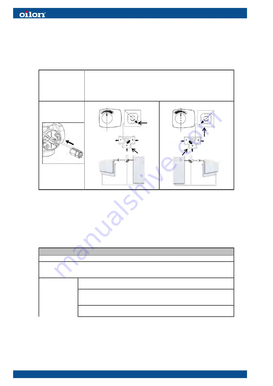
Valve and actuator Installation
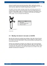
Below is a general description of how to install an Esbe VRG130 series control valve
and the associated Esbe ARA600 series actuator. Other valves are installed in a
similar way. For more detailed instructions, please refer to the guide delivered with the
valve and actuator.
Align the bevel on the
valve stem with the slot
on the actuator shaft.
Turn the valve stem to a position corresponding to the piping connection.
● Pay attention to the flow directions and the markings on the valve (triangle,
circle and square).
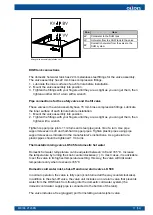
Install the scale plate at this stage as well.
● Note that when installing the actuator, the actuator control knob must be in
the middle position.
ESBE valve stem ver. 1
A
B
The installation guide delivered with the valve includes other connection options.
Enabling the control valve
Enable the valve from
Initial setup
settings (see chapter
Commissioning
) or from
Heating
settings (see the table below). Enable the valve by selecting
Valve control
as
the setting for the circuit.
DEVICE SETTINGS → SERVICE → HEATING
→ HEATING CIRCUIT 1
The heating circuit takes the heating energy either directly from the heat pump’s condenser or its buffer
tank. The Connection setting determines which method is used. This option, in turn, allows you to select
the equipment installed in the circuit. The settings for Circuit 2 and 3 are identical to Circuit 1 settings.
No
The circuit is not in use.
Direct connection
The heat pump is connected directly to the building’s heating system. The system
has no circulation pump or control valve that would be controlled by the heat pump.
Circuit used
Direct connection, with pump
The system has a circulation pump which is controlled by the heat pump.
26 (54)
M8006 2123EN
Содержание CUBE 10 EasyAce
Страница 1: ...M8006 2123EN 10 June 2021 CUBE and ECO INSTALLATION AND COMMISSIONING...
Страница 2: ......
Страница 51: ...Pump curves Wilo Yonos PARA GT 7 5 Grundfos UPMXL GEO 25 125 M8006 2123EN 49 54...
Страница 57: ......


