Connections (CUBE)
The connections for the sensor are indicated in the unit’s electric diagram. Connect the
sensor to terminal block X3’s terminals 4 and M (either wire in either terminal).
Installation (CUBE, ECO)
The heating circuit 1 flow sensor (TE212) is used to control the circuit’s control valve
(FV222). The sensor can be installed in the heating circuit’s flow line, even if there is
no valve to be controlled by the heat pump; this will allow the sensor’s reading to be
viewed through the automation system. If you do not install the sensor in the flow line,
disconnect the sensor’s wires from the heat pump’s switchboard and protect the bare
wire ends. You can otherwise leave the sensor in place.
Install the sensor in the heating circuit flow line as indicated in the piping diagram.
Place the sensor in a way that allows it to measure the temperature in the flow line as
accurately as possible.
Install the sensor 0.5–2.0 m downstream from the control valve. Install the sensor
preferably downstream from the circulation pump. If the sensor is too close to the
valve, its readings will be inaccurate, and placing the sensor too far downstream will
cause harmful control delay.
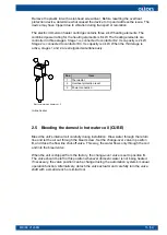
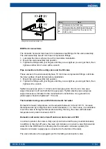
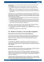
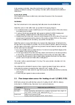
Attach the sensor to a metallic pipe surface or in a metallic sensor pocket in the pipe.
Surface installation
● Attach the sensor firmly and securely against the pipe surface along the entire
length of the metal sleeve covering the sensor probe.
● Finish by adding thermal insulation to insulate the sensor from ambient air
temperature.
● If necessary, use thermal paste between the sensor probe and the pipe surface.
● It is advisable to attach the sensor along the pipe surface at the 3 o’clock or 9
o’clock position.
Installation in a sensor pocket
Iinstall the sensor in a pocket intended for 6 mm probes.
If the pipe has a small diameter, create a 90 degree turn in the line flow direction with
a tee fitting. Place the sensor pocket in the outlet that is parallel to the original line. The
probe itself should extend upstream from the turn. This will allow you to install even a
long sensor pocket (150–200 mm) along the line. The sensor pocket is available as an
accessory, see section
Accessories.
24 (54)
M8006 2123EN
Содержание CUBE 10 EasyAce
Страница 1: ...M8006 2123EN 10 June 2021 CUBE and ECO INSTALLATION AND COMMISSIONING...
Страница 2: ......
Страница 51: ...Pump curves Wilo Yonos PARA GT 7 5 Grundfos UPMXL GEO 25 125 M8006 2123EN 49 54...
Страница 57: ......


