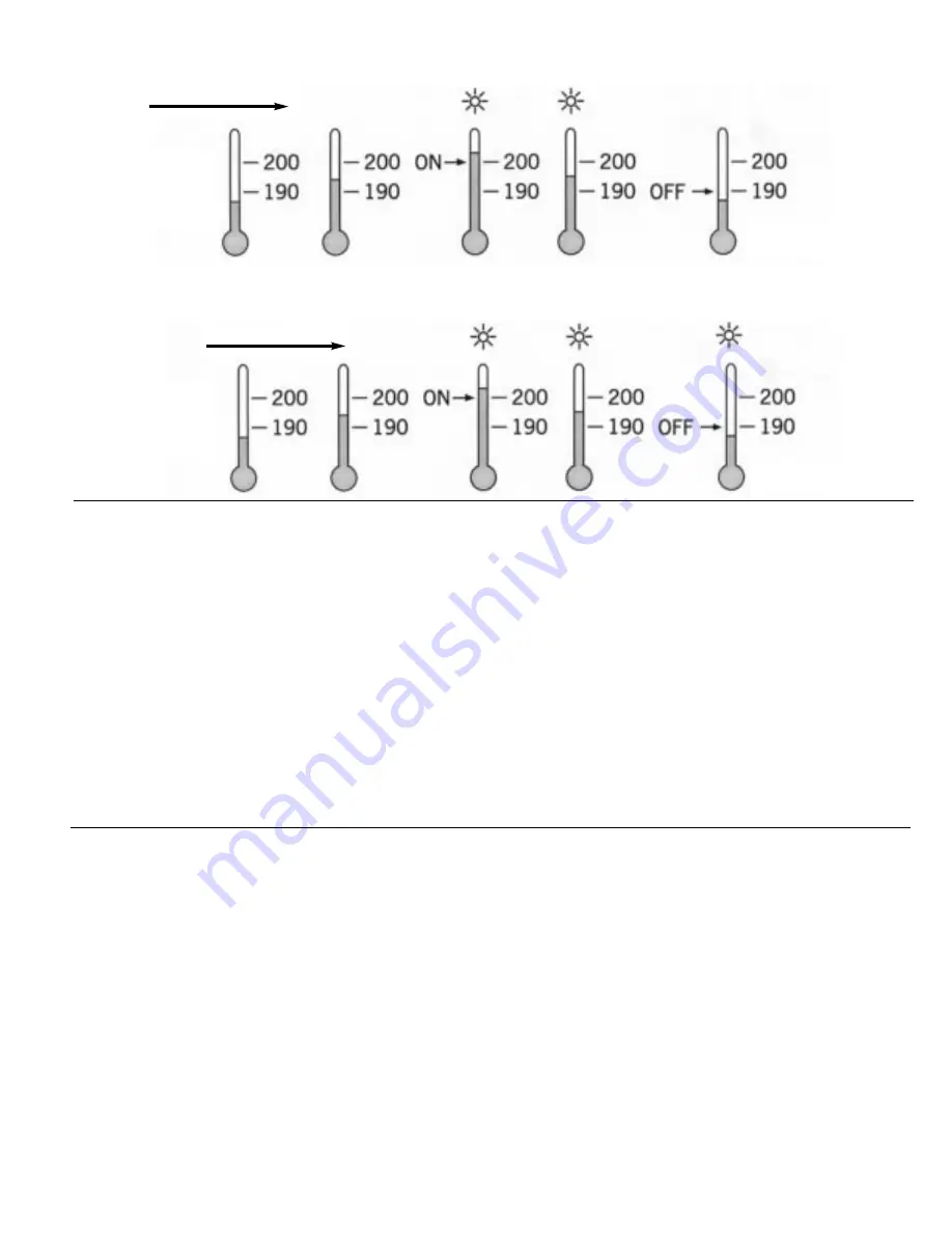
Figure 5.7
Latching Process Alarm
Figure 5.6
Normal Process Alarm
Process Proceeds
Process Proceeds
SP2 = 200
AL.HY = 10.0
AL.MD = LTCH
AL.FN = PV.H.A
Process Alarms
The output 2 will perform process alarm functions by
selecting ALM for OUT2 and PV.H.A or PV.L.A for AL.FN.
If PV.H.A is selected, the alarm will perform process high
alarm. If PV.L.A is selected, the alarm will perform
process low alarm. The process alarm sets an absolute
trigger level. When the process exceeds that absolute
trigger level, an alarm occurs. The taller level is deter-
mined by SP2 (Set point 1 value) and AL.HY (Alarm hys-
teresis value). The hysteresis value is introduced to avoid
interference action of alarm in a noisy environment.
Normally AL.HY can be set with a minimum value (0.1).
Trigger levels for process high alarm are SP2 and SP-
AL.HY. Trigger level for process low alarm are
SP2+AL.HY and SP2.
Signal Conditioner DC Power Supply
Three types of isolated DC power supplies are available
to power an external transmitter or sensor. These are 20V
rated at 25mA, 12V rated at 40mA and 5V rated ar 80mA.
The DC voltage is delivered to the output 2 terminals by
selecting DCPS for OUT2 in set-up menu.
Limit Annunciator
If L.AN (Limit Annunciator) is selected for OUT2, output 2
will act as a Limit Annunciator. If the limit is or has been
reached and he REST key (or remote reset contacts) has
not been preset, then the limit annunciator output will be
energized and the OP2 indicator will be lit and remain
unchanged until the REST key or remote reset input is
applied.
RS-485 Communication
Using a PC for data communication is the most econom-
ic way. The signal is transmitted and received through the
SP2 = 200
AL.MD = NORM
AL.HY = 10.0
AL.FN = PV.H.A
17
There are two types of alarm modes that can be
selected, these are: normal alarm and latching alarm.
Normal Alarm: AL.MD = NORM
When a normal alarm is selected, the alarm output is
de-energized in the non-alarm condition and energized
in an alarm condition.
Latching Alarm: AL.MD = LTCH
If a latching alarm is selected, once the alarm output is
energized, it will remain unchanged even if the alarm
condition has been cleared, unless the power is shut
off or the RESET key (or remote reset button) is
pressed.
Failure Transfer: AL.FT - OFF or ON
In a case of Sensor Break or A-D Failure, the alarm
output will be on or off according to the selection of
AL.FT.
PC serial communication port (generally RS-232).
Since a standard PC does not support and RS-485
port, a network adapter (such as SNA10A, SNA10B)
has to be used to convert RS-485 to RS-232 when
RS-485 is required for data communication. Many RS-
485 units (up to 247 units) can be connected to one
RS-232 port. In other words, a PC with 4 comm ports
can communicate with 988 units. Ogden uses a
Universal MODBUS RTU MODE protocol to commu-
nicate via RS-485.
Set up
1. Select COMM for OUT2
2. Select an unequal address (AR) for those units
which are connected to the same port.
3. Set the Baud Rate (BAUD) and Parity Bit (PARI) so
that these values are accordant with PC set up
conditions.


