Control Systems
OBR Control Systems Inc
OBR Control Systems Inc
Telephone : +1 (248) 672-3339
32233 West 8 Mile Road
www.obrcontrolsystems.com
Livonia, Michigan 48152
USA
57 / 92
11.1.4
Termination
To function correctly a CAN bus requires a termination resistor between the two CAN wires.
This is done by fitting two 120 Ohm termination resistors between CAN H and CAN L, one each
end of the CAN string.
All additional modules having CAN communication which will be connected to the CAN bus must
have their termination resistors disabled. It is essential for the stability of the CAN bus that two and
only two resistors are fitted.
It is possible to enable internal termination resistors in PCM2, terminating one end of the CAN
string.
Each CAN bus can be individually terminated. By ticking the box, a 120 Ohm resistor within PCM2
is connected between CAN H and CAN L on the selected CAN bus.
Please note that a CAN connection should not exceed 16 metres (for 1 Mbits/s baud rate).
CAN wires must be laid out as twisted pairs.
This must be respected for each individual CAN bus.
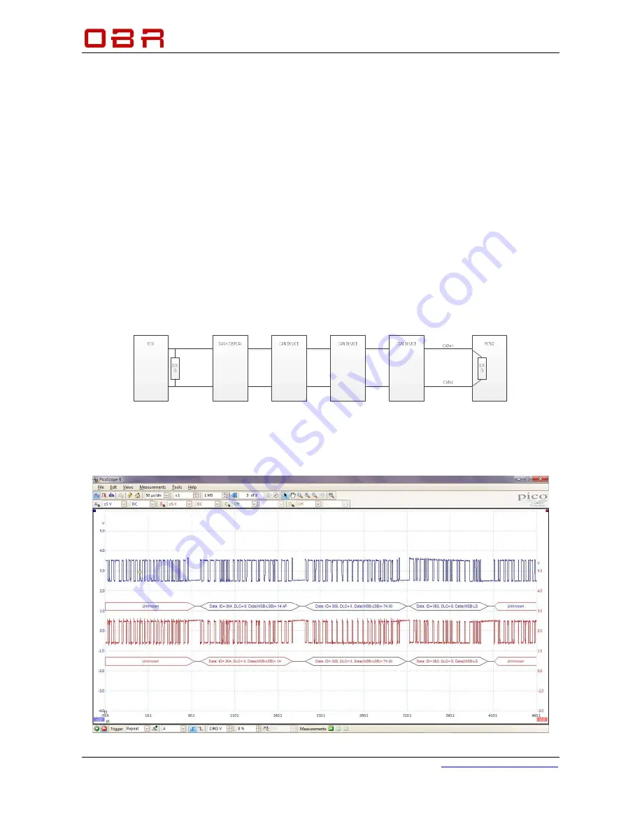
The diagram shows an example of the correct layout of a CAN bus. The devices should be daisy
chained and not starred. The termination resistors should be at the extreme ends of the bus. The
diagram shows the two terminating resistors one physical resistor added to the cable near the ECU
and the second internal termination in the PCM2.
11.1.4.1
Correctly Terminated CAN Bus
It is very important that a CAN bus is terminated correctly. If it is terminated with 1 or 3 resistors,
the data exchange will not work correctly and the car will have serious running issues.
Please note the oscilloscope screen shot displaying a
correctly
terminated CAN bus:


