


MSC711x Application Development System (MSC711xADS) Reference Manual, Rev. 1
6
Freescale Semiconductor
Overview
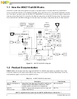
1.1 How the MSC711xADS Works
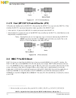
The MSC711xADS allows the application engineer to upload software to both the MSC7116 and MPC8272
devices and run that software with emulated debugging devices (JTAG or a PC). The software application can run
in a “bare bones” operation with only the MSC7116 and MPC8272 processors or with various input or output data
streams, such as from the E1/T1 connection, the Ethernet connections, or the PSTN connections. You can analyze
the results with the CodeWarrior debugger or directly analyze the input or output data stream via other methods.
Figure 1-3. MSC711xADS Block Diagram
1.2 Product Documentation
Table 1-2
lists the documentation that supports the MSC711xADS. Documentation is available from a local
Freescale distributor, a Freescale semiconductor sales office, or a Freescale Literature Distribution Center. For
documentation updates, visit the Freescale DSP web site.
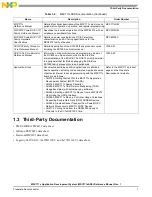
Table 1-2. MSC711xADS Documentation
Name
Description
Order Number
MSC711xADS Reference
Manual
Detailed functional description of the MSC711xADS board,
including memory and peripheral configuration, switch
settings, operation, connections, and programming.
MSC711xADSRM
MSC711x
Technical Data
MSC711x features list and physical, electrical, timing, and
package specifications
MSC711x
Expansion Header
J1
J2
J4
H.110
MSC7116
OCE10
UART
DDR
HDI16
DDR
DDR
16 MB
16 Bits
MPC8272
PCI
COP
60x Bus
SDRAM
(64 MB)
512
TS Switch
RJ45
RJ45
10/100
PHY
RJ45
16/8 Bit
A
D
16 Bit
SCC
FCC
RS-232
10/100
PHY
8 Bit
Flash
Memory
16 Bit
BCSR
T1/E1
Framer
8 Bit
SLICK
SLACK
RJ11
RS-232
9-Pin
9-Pin
16 Bit
I
2
C
EEPROM
D
A
B
A
D
32
XB
60x Bus
Mictor
Mictor
TDM
MAC
2 TDM
Parallel
EPP-to-JTAG
OCE10
COP