


MSC711x Application Development System (MSC711xADS) Reference Manual, Rev. 1
42
Freescale Semiconductor
MSC711xADS Interfaces
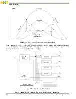
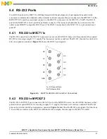
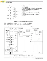
Figure 5-4. MPC8272 RS-232 Serial Port Connections
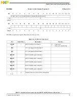
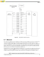
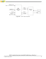
5.5 JTAG/OCE10 Test Access Port (TAP)
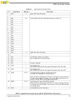
A block diagram of the JTAG connection and I
2
C boot EEPROM is shown in Figure 5-5.
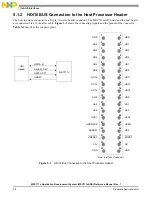
Figure 5-5. Parallel Port Connection, JTAG, and I
2
C
• DCD (O). Data Carrier Detect. This line is always asserted by the
MSC711xADS.
• TX (O). Transmit data.
• RX (I). Receive data.
• DTR (I). Data terminal ready. Software on the MSC711xADS uses
this signal to detect whether a terminal is connected to the
MSC711xADS board.
• DSR(O). Data set ready. This line is always asserted by the
MSC711xADS.
• RTS (I). Request to send. This line is not connected in the
MSC711xADS.
• CTS (O). Clear to send. This line is always asserted by the
MSC711xADS.
1
2
3
4
5
6
7
8
9
GND
DTR
RX
TX
DCD
DSR
RTS
CTS
N.C.
14-Pin OCE10 Header
MSC711x
Device
JTAG
16-Pin JTAG Header
MPC8272
Device
JTAG
JTAG
Signals
I
2
C
TDO
TDI
TDO
JTAG Bus
TDI
SCI, SDA
Parallel Port
Voltage
Transceiver
PLD
Address
Latch,
Decoder,
And
I
2
C
Transceiver
JTAG
TAP
Master
74LVX161284
(Fairchild)
Altera
(Series 3000)
SN74LVT8980A
(TI)
A[0–2]
D[0.7]
CTL
256 KB
Serial
EEPROM
M24256
Jumper
JTAG_EPP
JTAG_SERIAL
JTAG_ExtConv
I2C_PP
I2C_CPU
SCL, SDA
SCL
SCL
Write
Protect
I
2
C