


MSC711x Application Development System (MSC711xADS) Reference Manual, Rev. 1
22
Freescale Semiconductor
Hardware Configuration and Boot
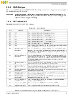
LD6
MSC711x MII/TDM2
enable
Green. Indicates whether the MSC711x MII/TDM port is connected to the TDM
device/Ethernet PHY.
LD7
MSC711x MII enable
Green. The MSC711x MII/TDM2 port is connected to the Ethernet PHY in MII
mode.
LD8
MSC711x TDM2 enable
Green. The MSC711x MII/TDM2 port is connected to the TSI and/or Ethernet
PHY in RMII mode.
LD22
Parallel port connection in
SPP mode
Green. The board is connected directly to the PC parallel port in SPP mode and
the COP/JTAG connector (P14) is irrelevant.
LD21
Parallel port connection in
EPP mode
Green. The board is connected directly to the PC parallel port in EPP Mode and
the COP/JTAG connector (P14) is irrelevant.
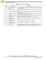
LD24
External debugger
connection
Green. A command converter can be connected to the COP/JTAG connector
(P14).
LD23
I
2
C EEPROM MSC711x
connection
Green. The MSC711x is connected to the I
2
C EEPROM.
LD20
I
2
C EEPROM parallel
port connection
Green. The parallel port is connected to the I
2
C EEPROM.
LD17
Debug mode
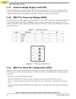
Green. Indicates whether the MSC711x is forced into Debug mode using SW4-1
(see
Section 2.4.2
, MSC711x Power-Up Settings (SW4), on page 12).
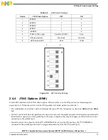
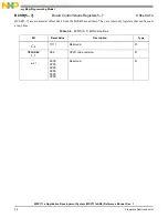
Table 2-10. LED Indicators (Continued)
LED
Indication
Description