background image

Service manual  

XLP 504 / XLP 506

05/2018 | 06

245

Appendix

INSTALLING A GENERIC PRINTER UNDER WINDOWS 7

A firmware update via data line requires a „Generic printer“ to be installed on the host computer 
running under Windows 7. Follow this installation instruction:

1. Click START > DEVICES AND PRINTERS > ADD PRINTER.
2. Click ADD A LOCAL PRINTER.
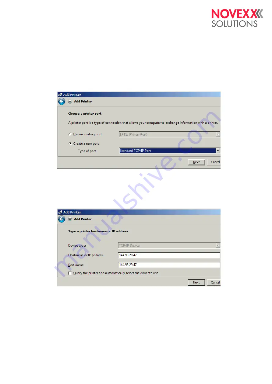
3. In the dialog „Choose a printer port“ select STANDARD TCP/IP PORT (alternativley USB 

PORT, if a USB line is connected) [171]. Click NEXT.

[171] Choose a printer port.

4. Enter the IP address of the machine into the field HOSTNAME OR IP ADDRESS [172]. Click 

NEXT.

IP adddress see 

Interface > Network > IP address

The checkbox „Query the printer [...]“ must not be activated.

[172] Assigning an IP address.

Содержание XLP 504

Страница 1: ...Edition 9 5 2018 Translation of original version SERVICE MANUAL XLP 504 XLP 506 Label printer ...

Страница 2: ......

Страница 3: ...Thermotransfer Ribbon 19 Connections device data 19 Interfaces 19 Electronic Configuration 19 Specifications for dispenser 20 Ambient Conditions 20 Certificates and Markings 20 XLP 506 Print width limitations 20 Service Mechanics 22 Housing components 22 Overview 22 Front hood 23 Rear hood 23 Front left housing 24 Bottom housing sections front rear side 25 XLP 504 Ribbon mandrels 26 Exploded drawi...

Страница 4: ...or 51 Retrofitting the internal rewinder 52 Installing the dispensing edge 55 Installing the baffle plate 56 Dispensing edge sensor 57 Parameter settings 58 Replacing Electronic components 60 Important information 60 Control panel board 60 CPU board 61 Output stage of stepper motor 62 Output stage of BLDC motor 63 I O board 64 Power supply 65 Service Electronics 67 Handling Boards 67 ESD protectio...

Страница 5: ... notes 94 Sensors on the CPU board 95 Sensors on the stepper motor output stage board 96 Sensors on the BLDC motor output stage board 96 Sensors on the I O board 96 Settings 98 Sensor settings 98 Setting sensors 98 Setting the material end sensor 101 Adjusting the imprint position 102 Prerequisites 102 Compensating length misalignment 102 Compensating impression misalignment 103 Parameter Menu 104...

Страница 6: ...Storing on memory card 226 Firmware 227 Notes About Firmware 227 Please note 227 Detecting the firmware version in the printer 227 Updating firmware 228 Notes about the update procedure 228 Update from a memory medium 228 Update via data interface 229 Forced bootloader start 230 Appendix 231 Setup file for XLP 504 231 Wiring diagrams 238 XLP 504 basic 239 XLP 504 basic 600 dpi 240 XLP 50x basic di...

Страница 7: ...les partner Technical release Technical release 4 2018 Software version 7 75 Liability NOVEXX Solutions assumes no liability for damages resulting from improper adjustments or re pairs of the machine It is assumed that only knowledgeable and appropriately qualified persons are to perform installation adjustment or repairs Copyright NOVEXX Solutions retains all rights to this manual and its appendi...

Страница 8: ...tions as well as additional infor mation Notes about hazards and risks Important instructions that must absolutely be followed are specially highlighted Illustrations Illustrations appear in the text where required References to these illustrations are shown in square brackets containing the number of the illustrations Uppercase letters after an illustration number for example 12A refer to the cor...

Страница 9: ...ial number can be found on the rating plate of the machine as illustrated below 1 1 Rating plate of an XLP 504 The printer bears the serial number 106378 Printer state Key combination Function Startup 1 2 3 Start without motion control 3 4 Enter access code after startup see chapter Access authoriz on page 136 1 4 Start bootloader see chapter Forced bootloader start on page 230 Home screen 1 3 4 E...

Страница 10: ...ce data of the printer Some of the coun ters contained therein such as the meterage of the print head are incremented automatically Oth er counters such as the number of print head replacements must be manually incremented by the service technician This is done by opening the corresponding parameter Tab 2 Reset all counters Open Tools Service Serv data reset Menu Parameters Run to Tools Service Se...

Страница 11: ...ns and all other notes carefully Observe the additional safety and warning notes on the printer Qualifications required Trained staff is required for inserting and changing foils and material Users need to be instructed in the use of the printer so they can work safely and independently Users should be able to resolve minor operational issues and faults by themselves At least two users should be i...

Страница 12: ...nded power socket fitted to authorized standards Connect only devices to the interfaces at the printer that fulfil SELV safety extra low voltage circuit requirements according to EN 60950 Protection against injuries by mechanical action Only operate the printer when the cover is closed Don t wear loose long hair if necessary wear a hairnet Keep loose jewellery long sleeves etc away from rotating p...

Страница 13: ...lace missing or illegible warning notes Warning note Meaning Article no The Pinch point warning note warns you of the danger po sed by the machine s rotating parts they can trap items and draw them in A5346 The Hot surface symbol warns of a burn hazard if the sur face is touched Allow the device to cool off before touching it A5640 The blue label Read manual demands that operators read the user ma...

Страница 14: ...eight W Width D Depth Weight Performance Data Print head Print Technology Thermodirect and thermotransfer printing Print head Type Flat Head Type ceramic thin film flat head Printer Weight XLP 504 basic peripheral 14 0 kg XLP 504 basic dispenser peripheral dispenser 14 7 kg XLP 506 basic peripheral 15 5 kg XLP 506 basic dispenser peripheral dispenser 16 5 kg 406 463 57 3 98 3 50 153 12 25 315 267 ...

Страница 15: ...in is unprintable Printer Resolution Dot mm Resolution dpi Printspeed mm s Printspeed inch s Max printwidth mm XLP 504 8 0 203 50 254 2 10 104 11 8 300 50 200 2 8 105 7 23 6 600 50 150 2 6 105 6 XLP 506 8 0 203 50 200 2 8 168 11 8 300 50 150 2 6 CAUTION Hazard of malfunction of the power supply and restart of the printer XLP 506 Take into account the limitations regarding print contrast and print ...

Страница 16: ...egrees Impression accuracy 5 The impression accuracy depends on the print position on the label the longer the distance to the gap is the lower is the impression accuracy The maximum impression accuracy is at the gap position with 1 mm Reading examples A Print positioin 1 is located 50 mm behind the gap position The maximum possible deflection from the theoretical print position is 1 5 mm B Print ...

Страница 17: ... CC bar codes Printer emulation Easy Plug Codabar Code 128 A B C Code 128 Code 128 UPS Code 128 pharmacy ITF Code 2 5 matrix MSI Code 2 5 interleaved EAN 8 Code 2 5 5 line EAN 13 add on 2 Code 2 5 interleaved ratio 1 3 EAN 13 add on 5 Code 2 5 matrix ratio 1 2 5 EAN 128 Code 2 5 matrix ratio 1 3 Postcode guide and identity code Code 39 UPC A Code 39 extended UPC E Code 39 ratio 2 5 1 Code 93 Code ...

Страница 18: ...504 15 120 mm XLP 504 dispenser 30 110 mm a a The material passage width is limited by the dispensing sen sor which is mounted at the side If a dispensing edge without a sensor is applied foot switch operation the passa ge width is as large as at the standard printer XLP 506 50 185 mm XLP 506 dispenser 50 170 mm a Tab 5 Overview material width Printer Min length Max length XLP 50x 5 mm max print w...

Страница 19: ... 110 mm XLP 506 54 172 mm Protection class I Mains Voltage 100 240 V AC Mains Frequency 60 50 Hz Power Consumption Max 320 W In standby mode depending on the equipment 30 40 W Current Consumption 3 0 1 5 A RS 232 Baud 1200 115200 8 bit suitable connection cord 1 1 D Sub 9 extension lead connector jack RS 422 485 On optional I O board D Sub 15 Baud 1200 115200 8 bit Ethernet 10 100 Base T with TCP ...

Страница 20: ...ispensing edge print zero line 25 mm Distance punch sensor print zero line 71 mm Max admissible outer diameter of the rewound backing paper roll 120 mm Installation location Inside buildings Protected from wind and spray water Dry Not in areas with potentially explosive atmosphere Operating Temperature 5 to 35 C Storage Temperature 4 to 60 C Relative Humidity 35 75 non condensing Protection catego...

Страница 21: ...int contrast at print width 100 mm 105 Max admissible print width at print contrast 105 100 mm 127 5 Max admissible print contrast at print width 75 mm 88 Max admissible print width at print contrast 88 75 mm 152 6 Max admissible print contrast at print width 65 mm 74 Max admissible print width at print contrast 74 65 mm Tab 9 XLP 506 Print width limitations for 300 dpi printheads ...

Страница 22: ... 03 22 Service Mechanics Service Mechanics HOUSING COMPONENTS Overview 6 Housing components of the XLP 50x A Rear hood B Rear bottom housing C Front hood D Flange cover E Front bottom housing F Plug cover G Front left housing A B C D E F G ...

Страница 23: ... hood Tools Torx screwdriver size 20 Removing 1 Open the front hood 2 Remove the three bolts 8A on the inside 3 Close the front hood 4 Remove the three bolts 9A on the outside 5 Remove the rear hood 9 First lift the rear hood from the rear end until the catch 9B is free Perform the installation in the reverse order to the re moval 7 The front hood is fixed with 4 bolts A 8 The rear hood is attache...

Страница 24: ... Screw off the nut Remove the retaining ring and the washer 11A 5 Carefully lift the housing Unplug the connector 11B from the control panel board Remove the housing Installation Perform the installation in the reverse order to the re moval Note the following Plug in the connector again before assembling Assembly sequence at stud bolt Base plate wash er retaining ring nut 10 Fixing bolt at the fro...

Страница 25: ...t housing section 2 Lightly pull the housing section outwards and care fully lift it upwards 13A The two plastic catches 13A per housing section reach into the openings on the printer baseplate Do not break off the catches Perform the installation in the reverse order to the re moval 12 Fixing screws of the bottom housing parts 13 Catches A at the bottom side of each housing section A A A B A ...

Страница 26: ...Service manual XLP 504 XLP 506 05 2018 03 26 Service Mechanics XLP 504 RIBBON MANDRELS Exploded drawings 14 Ribbon unwinding mandrel 15 Ribbon rewinding mandrel ...

Страница 27: ...ging the adapters is the same on both ribbon mandrels Tool Screwdriver medium size Removing 1 Remove the lock washer 16A 2 Remove the shim ring 16B and the core adapter Installation Perform the installation in the reverse order to the re moval Note the following Turn the outer core adapter so that the wings 17A show in the same direction as those at the inner adapt er 16 Core adapters C D at the r...

Страница 28: ...al Note the following Assembly sequence See figure 19 Place the 3 springs with 3 holes distance each into the holes on the disk 21 Put some grease on the springs to prevent them from falling out Make sure that the eyelet at the brake package shows downwards 18 Shim ring on the inside DIN 988 12x1x18 Refasten the retaining spring The ribbon mandrel must move easily so that the retaining spring can ...

Страница 29: ...r 22B 2 Open cable clamps cut cable ties Remove cable from cable clamps 3 Unplug end of cable from CPU board Installation Perform the installation in the reverse order to the re moval Note the following Connect sensor to plug CN906 23A on CPU board For a detailed connection diagram see chapter Wiring diagrams on page 238 Install the cable so that it does not contact any mov ing parts 22 Ribbon end...

Страница 30: ...n mandrel out of the bearing as shown 26 Installation Perform the installation in the reverse order to the re moval Note the following Assembly sequence See figure 25 Shim ring on the inner side DIN 988 12x0 5x18 Place the 3 springs with 3 holes distance each into the holes on the disk 27 Put some grease on the springs to prevent them from falling out After assembling set the assembly braking torq...

Страница 31: ...antly at the spring balance until the ribbon mandrel starts to turn 28 At the same time read the tractive force from the spring balance While measuring the ribbon rewinding mandrel you must block the print roller hold it manually 5 If the measured value is above or below the set point correct the setting as shown in figure 29 6 Repeat the measurement until the measured value matches the setpoint R...

Страница 32: ...Service manual XLP 504 XLP 506 05 2018 03 32 Service Mechanics XLP 506 RIBBON MANDRELS Exploded drawings 30 Ribbon unwinding mandrel 31 Ribbon rewinding mandrel ...

Страница 33: ...nging the adapt ers is the same on both ribbon mandrels Tool Screwdriver medium size Removing 1 Remove the lock washer 16A 2 Remove the shim ring 16B and the core adapter Installation Perform the installation in the reverse order to the re moval Note the following Turn the outer core adapters so that the wings 17A show in the same direction as those at the inner adapt er 32 Core adapters C D at th...

Страница 34: ...ve the sensor Leave the sensor cable connected 3 Detach the spring 34B from the top end 4 Measure and note the screw in depth of nut and cap The values determine the setting of the ribbon brake 5 Remove the nut 36A 6 Turn the threaded rod 36B at the read hex head out of the cap 36C and pull it out of the ribbon mandrel Remove the cap Continued overleaf 34 Braking mechanism for ribbon unwinding man...

Страница 35: ...ent them from falling out Slightly grease the disk at its inner diameter 39B before mounting it Shim ring on the inside DIN 988 12x1x18 Refasten the retaining spring The ribbon mandrel must move easily so that the retaining spring can rotate it back to its initial position When refastening the sensor make sure that the timing disk engages into the fork without touching it After assembling set nut ...

Страница 36: ...r 40B 2 Open cable clamps cut cable ties Remove cable from cable clamps 3 Unplug end of cable from CPU board Installation Perform the installation in the reverse order to the re moval Note the following Connect sensor to plug CN906 41A on CPU board For a detailed connection diagram see chapter Wiring diagrams on page 238 Install the cable so that it does not contact any mov ing parts 40 Ribbon end...

Страница 37: ... off the lower toothed belt pulley and remove it 24A 3 Measure and note the screw in depth of nut and cap 43 The values determine the setting of the ribbon brake 4 Remove the nut 42A 5 Turn the threaded rod 44A at the read hex head out of the cap 44B and pull it out of the ribbon mandrel Remove the cap Continued overleaf 42 Braking mechanism for ribbon rewinding mandrel 43 Measure the screw in dep...

Страница 38: ...on the inner side DIN 988 12x0 5x18 Place the springs with 2 holes distance each into the holes on the disk 47A Put some grease on the springs to prevent them from falling out Slightly grease the disk at its inner diameter 47B before mounting it After assembling set nut and cap to the screw in depth noted before or newly set the braking torque see chapter Setting the braking torque on page 31 45 P...

Страница 39: ...ange for the tractive forces on rewind and un wind mandrel Measuring the tractive force 1 Push a cardboard sleeve on the ribbon mandrel 2 Wind some fabric ribbon around the cardboard sleeve 3 Fix the end of the fabric ribbon 49B to the spring balance 49A 4 Pull constantly at the spring balance until the ribbon mandrel starts to turn 49 At the same time read the tractive force from the spring balan...

Страница 40: ... 50B If the closing lever 50C is closed the pressure pads will press the print head against the print roller Tools Torx screwdriver sizes 10 and 20 Removing 1 Remove the rear hood See chapter Rear hood on page 23 2 Remove fastening bolt 52A from switch flag Remove the switch flag 52B Continued on next page 50 Print head pressure shaft A with pressure pads B and closing lever C at the XLP 504 51 Pr...

Страница 41: ...ressure pad from the pressure shaft 8 Remove the parts 54D out of the pressure pad housing Installation Perform the installation in the reverse order to the re moval Note the following Assembly sequence See fig 54 Lubricate at the shown positions Intallation of washer DIN 988 5x10x1 54E only at the outer pressure pad part no A4631 Intallation of washer DIN 988 5x10x1 part no A4631 54E XLP 504 Inst...

Страница 42: ... off the sensor 55A 2 Open cable clamps cut cable ties Remove cable from cable clamps 3 Unplug end of cable from CPU board Installation Perform the installation in the reverse order to the re moval Note the following Connect the sensor to plug CN 907 56A on CPU board Install the cable so that it does not contact any mov ing parts 55 Closing lever sensor A 56 Connection from closing lever sensor to...

Страница 43: ...uide moves At the same time read the tensile force driving force Setpoint 8 2 N When the measured driving force deviates from the set point Adjusting the driving force 1 Unscrew the cover 58B 2 By rotating the set screw 58C in the material guide you can increase or reduce the driving force Increase the driving force Tighten the set screw clockwise Reduce the driving force Loosen the set screw coun...

Страница 44: ...e the power supply see chapter Power supply on page 65 2 Remove the screw 61A and take off the shaft 61B Installation Perform the installation in the reverse order to the re moval Note the following Install the shaft Clean the thread hole on the shaft and the screw thread Loctite Cleaner 7063 cleaning agent Apply Loctite 243 glue to the screw thread Ob serve the handling instructions from the manu...

Страница 45: ...the cable 62A from the motor 3 Remove the three screws 62B Remove the mo tor Installation Perform the installation in the reverse order to the re moval Note the following Tighten the belt Press the motor downwards with the screws lightly tightened Tighten the screws Install the cable so that it does not contact any mov ing parts 62 Motor and drive belt on XLP 504 63 Motor removed A B ...

Страница 46: ...the printer swivel the cover 65B downwards 4 Pull out the sensor fork 65A While doing this carefully guide the cable through the opening in the printer separating panel Installation Perform the installation in the reverse order to the re moval Note the following Connect the label sensor to the CPU board 66A B Install the cable into the cable holder so that it does not contact any moving parts 64 C...

Страница 47: ... head and punch sensor If these short labels were to be printed in Real 1 1 mode loops could form as the material moves back wards As a consequence the printout could move on the label printing impressions would become impre cise In these cases we recommend installing the label sen sor described here This will improve the impressioning precision on short labels Requirements Printer XLP 504 Dispens...

Страница 48: ...ace the sensor as shown 69A Tighten the screw 69B When inserting the sensor make sure that the cable lies properly along the cast bolt 72A 72 Cable installation circle along cast bolt A 4 Insert the sensor cable through opening in case en closure 70A Continued on next page 68 Loosen the screw A 69 Label sensor A installed 70 Opening A in case enclosure A A B A A ...

Страница 49: ...A 6 Connect the sensor cable to CN909 on the CPU board 74A Fasten the cable with terminals and cable ties so that it does not contact any moving parts Activating the sensor Set Print Material Label sens type to Short label opt Adjusting the sensors See chapter Sensor settings on page 98 A 74 Connection from label sensor to CPU board A ...

Страница 50: ...5A from the motor pinion Remove the pinion 2 Remove the two set screws 75B from the plastic pinion Remove the pinion Installation Perform the installation in the reverse order to the re moval Note the following One of the two set screws must lie against the flat area of the shaft 76A Lubricate the teeth of the pinion 75 Gearbox of Rewinder Motor 76 Flat area A along motor axis A B A ...

Страница 51: ...motor and bracket 4 Remove the four screws 77C Remove the brack et 77D from the motor Installation Perform the installation in the reverse order to the re moval Note the following Connect the motor cable to the shown connector on the BLDC output stage board 78A Fasten the cable in place as shown using a cable tie 79 circle 77 Remove the rewinder motor B 78 Connector A for rewinder motor on BLDC po...

Страница 52: ...Push the rewinder modul 81B through hole in the separating wall 4 Align the rewinder module as shown and tighten it there 3x Torx M4x16 81C 5 Fix the cable using the cable holder in a way that it doesn t contact any moving parts 82 The cable only will be connected after installing the BLDC output stage see Installing BLDC output stage board into XLP 50x basic on page 54 Drucker XLP 504 Rewinding D...

Страница 53: ...Remove the feed motor See Replacing the feed motor on page 45 3 Feed the cable harness through the D Sub installa tion opening 84A 4 Fix the D Sub plug with 2 hex bolts 5 Install the cable 85A underneath the motor fasten ing domes as shown 85 circle 6 Feed the cable through the cable holder 86 circle 7 Connect the cable See cabeling diagram chapter Wiring diagrams on page 238 83 Installing the def...

Страница 54: ...t any moving parts Installing BLDC output stage board into XLP 50x peripheral 1 Screw the BLDC power stage board with heat sink to the left hand position 2x Torx DG 40x10 left next to the peripheral power stage board The solder side of the board is facing right 2 Connecting the board see chapter XLP 504 peri pheral on page 242 3 Fasten the cables so that they do not contact any moving parts 87 Ins...

Страница 55: ... the rewinder as follows Tool Torx screwdriver size 10 Procedure 1 Remove flange cover 89A front bottom housing section 89B and the tear off edge 89C See Housing components on page 22 2 Fasten the dispensing edge 90A using four screws 2x M3x8 2x M3x6 3 Connect and tighten the plug 90B of the dispens ing edge sensor 89 Parts to be removed 90 Installling the dispensing edge A B C A B ...

Страница 56: ...ocedure 1 Remove the front bottom housing section 91B and the tear off edge 91A See Housing components on page 22 2 Lightly turn in the two fastening screws 2x Torx M3x4 for the baffle plate by approx two turns 92A 3 Attach the baffle plate with the button holes of the baffle plate to the protruding screws 92B 4 Tighten the screws through the openings in the baf fle plate 91 Parts to be removed 92...

Страница 57: ...nsor does not have to be adjusted It is not possible to use a longer dispensing edge Testing the sensors See chapter Setting sensors on page 98 Pin configuration of D Sub connector 94 Pin Configuration 3 Collector 4 GND 5 VCC 5 V 93 Dispensing edge sensor A 94 Pin configuration for D Sub connector of dispensing edge sensor A 1 2 3 4 5 6 7 8 9 10 11 12 13 14 15 ...

Страница 58: ...topped and started Switching off Set Options Selection Periph device to None Switching the rewind function on off Prerequisites Only for XLP 50x with internal rewinder and baffle plate Insert label material before activating the rewinder otherwise an error message will appear Switching on Set Options Selection Periph device to Intern rewind er Don t confuse with the setting Rewinder which activate...

Страница 59: ...Internal Rewinder men us contain many special parameters for authorised ser vice technicians that are only visible after starting the printer in production mode Current mode Min rew current Max rew current Start rew curr Start cur len Pullback current Back diameter Break current Break diameter For details see chapter Parameter menu on page 34 ...

Страница 60: ...wdriver size 9 Removing 1 Remove the front left section of the enclosure See chapter Front left housing on page 24 2 Remove the four bolts 95A take off the board 95B Installation Perform the installation in the reverse order to the re moval Note the following Reconnect the cable before tightening the enclo sure section CAUTION Protect the electronic compo nents against damage from electrostatic di...

Страница 61: ...and 20 Removing 1 Unplug all cables from the board 2 Remove the two screws 96A from the rear side of the printer 3 Remove the top screw 96B 4 Remove the three screws 96C Remove the CPU board The bracket remains on the 96D board Installation Connect the board as shown in the cable diagram see chapter Wiring diagrams on page 238 A A B C C C D ...

Страница 62: ...tion Perform the installation in the reverse order to the re moval Note the following Install the board with the component side facing left 97 If your printer contains BLDC and stepper motor power stages XLP 504 peripheral dispenser the power stage of the stepper motor is installed on the right Connect the board as shown in the cable diagram see chapter Wiring diagrams on page 238 Make sure that t...

Страница 63: ...on in the reverse order to the re moval Note the following Install the board with the component side facing left 98 XLP 50x with one power stage The power stage is installed on the right XLP 50x with two power stages The BLDC motor pow er stage is installed on the left Connect the board as shown in the cable diagram see chapter Wiring diagrams on page 238 Make sure that the jumpers have been set p...

Страница 64: ...age 61 2 Unplug all cables from the board 3 Remove 2 screws from both the mounting plate 100A and board 100B and take off the board Installation Perform the installation in the reverse order to the re moval Note the following Connect the board as shown in the cable diagram see chapter Wiring diagrams on page 238 99 Position of I O board CPU board is removed 100 Fastening points of I O board A A B ...

Страница 65: ...e 23 2 Remove the CPU board See CPU board on page 61 3 If present Remove the I O board See I O board on page 64 4 If present Remove the pinion from the internal re winder See Replacing the pinion on page 50 101 XLP 504 with CPU board removed Removing the cable 1 Unplug the cable 101A from the motor power stage board s 2 Remove the cable 101B from the fastenings 101C A A B C C C ...

Страница 66: ...e three fastening screws of the power supply from the separating wall in the printer 3 Remove the power supply from the printer Installation Perform the installation in the reverse order to the re moval Note the following When installing make sure that no cables are clamped between the power supply and the separating wall of the printer Connect the power supply as shown in the cable di agram see c...

Страница 67: ...body using an ESD bracelet or other suitable means before touching a board If no suitable ESD protection is available touch an earthed object e g a hea ting radiator before touching a board Only place boards on earthed surfaces CAUTION The conducting tracks on the boards are very thin If a board is bent or warped the conducting tracks can easily crack Avoid bending or warping boards Avoid the use ...

Страница 68: ...Service manual XLP 504 XLP 506 05 2018 04 68 Service Electronics CPU BOARD Connections 105 CPU board connections A100150 A B C D E F G H I J K L M N O P Q R T U W Y Z AB AD S X AA V AE AC AF ...

Страница 69: ... CN910 D Sub harness marking AUX Q CN901 5 V supply voltage R CN503 RFID module option S BT801 Battery for realtime clock see chapter Lithium Battery on page 72 T CN1101 Ethernet 10 100 Base T see chapter Ethernet interface on page 71 U CN703 RS 232 see chapter Serial interface RS 232 on page 71 V JP701 Jumper connects 5 V 170 mA supply voltage to pin 9 at the RS 232 connector W CN403 USB device X...

Страница 70: ...t interface F Signal interface on optional I O board G Serial interface RS 232 422 485 on optional I O board For details about the optional interfaces 106F and 106G see chapter I O board on page 80 Foot switch connector 107 Connection diagram of the 1 4 3 point jack for foot switch connection USB host connector Pin Signal 1 VCC 2 Data 3 Data 4 GND A B C D E F G CN902 1 6 2 5 3 4 S R RN T TN S Ster...

Страница 71: ...cable article number A1207 Ethernet interface Setting of the transmission rate by autonegotiation Pin Signal 1 n c 2 Data 3 Data 4 GND Pin Signal 1 CD 2 RxD 3 TxD 4 DTR 5 GND 6 DSR 7 RTS 8 CTS 9 RI Pin Signal 1 TD 2 TD 3 RD 4 Termination 5 Termination 6 RD 7 Termination 8 Termination LED Meaning Green Lights high transmission rate 100 Mbit s Yellow Lights printer is connected to network Flashes ne...

Страница 72: ...at dust and other foreign substances will not cause shorting between the poles Pin Belegung 1 Anode 2 Kathode 3 Kollektor 4 Emitter 1 2 3 4 WARNING Danger of explosion if battery is incorrectly replaced Replace only with the same or equivalent type recommended by the manufacturer Take care of the correct polarity when replacing the battery Discard used batteries according to the manufacturer s ins...

Страница 73: ...de of rubber cotton etc to protect the battery from dirt 3 Take used battery out of the socket insert the new battery Take care of the correct polarity 108 108 Correct battery polarity 4 Reassemble the rear hood 5 Reconnect the printer to the mains and switch it on 6 Set time and date System Hardware Setup Realtime Clock ...

Страница 74: ... sensor of the peripheral device cable marking SENSOR 1 J4 110 Connection diagram sensor B Jumper J6 J1 J7 Caution Fig 109 doesn t show the correct jumper setting 111 Jumper J6 geschlossen C Connection for D Sub harness motor of the peripheral device cable marking MOTOR J3 112 Connection diagram motor D Connection CPU board J2 E Connection power supply J12 A C C D E C B A K GND C E GND J6 J1 J7 M ...

Страница 75: ...ver The firmware version of the installed peripheral output stage is displayed Updating firmware Updating the driver firmware is done the same way as with the printer firmware See chapter Firmware on page 227 The following file is required M5A_xx_ALL_downloadfile S3B for firmware version xx Connections settings 113 Connections of the output stage board M5A A7579 A Mounting bracket B Jumper for set...

Страница 76: ... 1 2 LED100 JMP100 1 U300 U100 D201 U201 J12 CE400 CE401 C R O S S 3 D 4 0 0 CE402 CE403 QN202 3 2 1 C 2 3 1 C 2 3 2 C 2 3 4 C 2 3 5 C 2 3 7 C 2 3 8 C 2 4 0 C 2 4 1 J3 4 1 U101 32 25 24 17 16 9 8 1 JP101 JP100 5 6 JP100 3 4 JP100 1 2 D D D D D D D D S D G S D G S D G S D G S D G S D G S D G S D G 110 P2 P1 K9C K2 K1 A U400 DZ300 1 3 2 R 3 1 0 R227 C236 R226 ST400 1 3 2 C230 R225 V I T E 3 C233 R22...

Страница 77: ...arness sensor of the peripheral device cable marking SENSOR 1 J4 B Connection for D Sub harness motor of the peripheral device cable marking MOTOR J3 C Connection CPU board J2 D Connection power supply J12 A K GND C E GND M A A B B 11 Reset 9 I2C SCL 1 Clock 0 10 I2C SDA 14 GND 1 5V 2 GND 3 n b 4 GND 5 38 54V 6 GND ...

Страница 78: ...the printout lists all mounted output stage boards with the installed firmware versions Updating firmware Updating the driver firmware is done the same way as with the printer firmware See chapter Firmware on page 227 The following files are required BLDC_Vx BAT resp BLDCAP54Vx S3B for firmware version x CAUTION Don t load the older firmware version 1 onto the new version 2 Connections settings 11...

Страница 79: ... 04 79 Service Electronics 117 Connection diagram sensor B Jumper J101 102 103 118 Jumpers J101 and J102 connected C Connection rewinder motor CN102 D Connection CPU board CN103 E Connection power supply CN104 A K GND C E GND J101 J102 J103 ...

Страница 80: ...S 232 or Centronics This is often realized in industrial plants where galvanic isola tion is required to avoid ground loops Signal interface If an applicator is applied with the printer this requires the exchange of control signals between printer and applicator Therefore signals like printing is finished have to be generated by the printer and the printer itself must wait for a signal like start ...

Страница 81: ... 10 11 12 13 14 15 GND 5V_EXT START_PRINT FEED PAUSE REPRINT 5VTO24V_EXT GND GND ERROR PRINT_END GND GND GND MACHINE_STATUS Signal Description Condition s for activating 5V_EXT 5 V supply voltage for external sensors START_PRINT Input Start signal for printing Setable by Options I O Board Start print mode All of the following conditions Online mode Printjob prevailing No error message FEED Input F...

Страница 82: ...nted labels 1 If REPRINT is activated while the printer is in pause mode PAUSE the reprint is executed only when the pause mode is cancelled All of the following conditions Online mode START_PRINT high 5VTO24V_EXT 5 24 V supply voltage for external sen sors ERROR Output Low if the printer is not ready to print High during the initialization of the printer One of the following conditions Pause mode...

Страница 83: ...ible connections to external electronics The input signals are supplied by an internal galvanically decoupled 5 V source Maximum admissible input voltages 0 to 24 V D C D C 5V 5V 24V 5V Eingang Masse Input signal Voltage range Current range Low VIL 0 1 V IIL 10 20 mA High VIH 40 24 V IIH 0 1 mA Tab 13 Characteristics of the input signals ...

Страница 84: ...ply V5 24 V 4 5 to 5 V at I 100 mA Maximum admissible output current 100 mA External electronics powered from this source must not consume more than 0 5 W External supply External supply V5 24 V 5 to 24 V at I 600 mA The I O board outputs may be powered by an external source from 5 V to 24 V pin 7 Maximum admissible output current 200 mA DC DC 24V 24V 24V 5V 5 24V 24V 24V 24V 5V 5 24V 5V Ausgang M...

Страница 85: ...t side Connection cable A2842 Both parts are required for the application Not all of the output signals on the USI board are also available on the I O board The pins of not available signals are grounded on the I O board The following signal lamps for outputs are there fore always lighting on the testbox RIBBON OUT MEDIA OUT WARNING Those inputs are not available on the I O board PLC ERROR TOUCH D...

Страница 86: ...n Signal Host Signal direction from I O board 1 DCD Short with DTR and DSR 2 RxD Out 3 TxD In 4 DTR Short with DCD and DSR 5 GND Masse 6 DSR Short with DTR and DCD 7 RTS In 8 CTS Out 9 RI Not connected Tab 15 Pin assignment RS 232 Pin Signal Host Signal direction from I O board 1 Not connected 2 Rx Out 3 Tx In 4 Term Termination 110 Ohm 5 GND Ground 6 Term Termination 110 Ohm 7 Tx In 8 Rx Out 9 No...

Страница 87: ...ns 3 and 4 Tx Pins 6 and 7 Tx RS 485 2 wire connection At each printer on the bus line connect the following pins inside of the cable connector Pins 2 and 3 Tx Rx Pins 7 and 8 Tx Rx Circuit diagram RS422 interface 126 Circuit diagram RS422 interface 6 4 7 3 8 2 6 4 7 3 8 2 GND 5V Tx Tx Tx Rx Rx Rx 110Ω Printer 1 Printer n appr 120Ω appr 1kΩ 4kΩ Last printer terminated RS 422 4 wire PC PLC ...

Страница 88: ...ervice Electronics Circuit diagram RS485 interface 127 Circuit diagram RS485 interface 6 4 7 3 8 2 6 4 7 3 8 2 GN D D5 VN T x D R 110Ω 5 5 Printer 1 Printer n ap t krinter terL inptes RS 485 2 wire Pmd Pam pkkrC120Ω pkkrC1 ΩC C 4 Ω pkkrC1 ΩC C 4 Ω ...

Страница 89: ...Service manual XLP 504 XLP 506 05 2018 04 89 Service Electronics OPERATION PANEL Connections 128 Operation panel board N100468 A Connection CPU board A ...

Страница 90: ...ware version for XLP 504 600 dpi at least 7 71 Connections LEDs 129 Power switch board for 600 dpi print head A Connection to CPU board CN1001 cable N100472 B Connection to power supply cable harness C Connection to print head cable A5639 D LED green Print head supply voltage on E LED yellow Print data is being transferred to the print head A B C D E ...

Страница 91: ...s for output stage boards 131 Pin assignment connections for output stage boards B Connection for CPU board 132 Pin assignment connection CPU board C Connection for print head 133 Pin assignment print head connection A B C GND 45V GND 5V 45V GND Power Fail Temp Sense GND 5V GND GND GND 45V 45V 24V 24V 24V 24V GND GND GND GND ...

Страница 92: ... by connecting the CPU board to the power supply At the 24 V and 45 V outputs no minimum output current is required to measure the voltages correctly Current range The 24 V output provides a continuous current of 6 A for 10 s in typical operation Without a minimum load at the 5 V output the voltage at 24 V and 45 V supply should not be higher than 28 V and 50 V respectively Output Range Max Min 45...

Страница 93: ...the printer can start to burn Only connect original Novexx Solutions peripheral devices to this interface Pin Signal 1 Emitter 2 GND 2 Collector 2 sensor input signal 3 Collector 1 sensor input signal 4 Emitter 1 GND 5 5 V supply voltage 6 45 V supply voltage 7 Motor A motor voltage 8 Motor A motor voltage 9 LED Kathode 2 light sensor 10 LED Anode 2 light sensor 11 LED Anode 1 light sensor 12 GND ...

Страница 94: ...sor is possibly dirty and has to be cleaned blow the dirt off with compressed air Check the sensor function e g by covering it If the displayed value doesn t change when the sensor is covered it is possibly not connected or defective General rule for all analog sensor values Full light leads to values 10 No light leads to values 220 To sensors which function as a switch applies the following Value...

Страница 95: ...paper in light barrier 140 255 Label material in light barrier 0 06 Optn 2 CN 910 0 255 analogous Reserved 0 07 H Temp CN 901 903 appr 100 140 Print head is very hot appr 141 255 Normal print head temperature 0 08 P Temp CN 701 Power supply temperature depends on the PS type 0 09 H Supp CN 901 903 0 No 5 V supply for print head b b Occurs e g if the print head is connected to the wrong connector o...

Страница 96: ...ispensing edge light barrier open 255 Dispensing edge light barrier covered 8 02 O Rew calculated Value 0 Ø of the backing paper rewinder roll is not known ca 35 120 Ø of the backing paper rewinder roll in milimeters Tab 21 Sensor test conditions for sensors which are connected to the BLDC motor output stage board Sensor Sensor name Connector Typical value Condition 15 01 Start CN 803 804 0 Start ...

Страница 97: ...quency more than 254 Hz 15 08 F100Hz CN804 0 APSF signal frequency 100 Hz 1 ca 140 Frequency in multiples of 100 Hz b a Is identical with 0 12 b Take care about the maximum frequency rating of the I O board Sensor Sensor name Connector Typical value Condition Tab 22 Forts Sensor test conditions for sensors which are connected to the I O board ...

Страница 98: ...ny material from the label sensor fork 3 Press the key Display 4 Increase or decrease the control value by pressing the or key until the read back value is in the range of 8 20 best at 13 15 5 Insert some standard material backing paper labels peeled off to verify the read back value Glossy side up The backing paper must cover the light barrier The read back value should match the range of 40 90 6...

Страница 99: ...the setting 6 Press the key to exit the parameter With this the ribbon sensor is set Print head lever sensor 1 Call the sensor setting dialog 2 Use the arrow keys to toggle to sensor 00 03 Lever 3 Press the key Display 4 Open and close the pressure lever by hand and watch the read back value Pressure lever open the value should match the range 5 7 Pressure lever closed the value should match the r...

Страница 100: ... the sensor setting dialog 2 Use the arrow keys to toggle to sensor 00 05 Short 3 Press the key Display 4 Remove any material from the label sensor fork 5 Increase or decrease the control value by pressing the Feed or Cut button until the read back value is in the range of 8 20 best at 13 15 6 Insert some standard material backing paper labels peeled off to verify the read back value The read back...

Страница 101: ...pter Setting sensors on page 98 Setting the materialend sensor 1 Call parameter Tools Adjustment Matend adjust 2 Take the label material out of the sensor fork 3 Set the value xx to 20 by pressing the or key All measured values below the set limit that is 20 are recognized by the electronics as ma terial end values lying above are recognized as only backing paper To be able to process transparent ...

Страница 102: ...ent 1 Insert recommended label material Print a feedadjust label call Tools Adjustment Feedadjust la bel 138 Feedadjust label with printed on measure scale C and calculation scheme D 2 Measure the distance between the two marks Start of meas 138B and End of meas 138E 3 Put the measured distance into the calculation scheme 4 Calculate Feedadjust Put the result into Tools Adjustment Feed adjust the ...

Страница 103: ...e Compensating impression misalignment 1 Print a feedadjust label call Tools Adjustment Feedadjust label 2 Measure the distance between leading label edge and Start of meas line 3 Identify the deviation from the target value 10 mm and type it in under Tools Adjustment Punch y calibr Positive values shift the print image against feed direction negative values shift it in feed direction 4 Print feed...

Страница 104: ...s only visible with activated Cutter Cutter 2000 Min rew current Punchmode Cut mode Max rew current Punchlevel Cut speed Start rew curr Label sens type Cut width Start cur len Mat end detect Cut position Pullback current Foil Double cut Back diameter Foil length Rest position Break current Outer foil diamet Rewinder d d Menu is only visible with activated external rewinder Rewinder 2000 Break diam...

Страница 105: ...P server Print Error Checking FTP Password Miss label tol Resolution Time client Gap detect mode Image Save Path Time server IP Singlestartquant Label Invert Sync interval Reprint function Commands Time zone Foil end warning Format Prefix Serial Port 1 Foil warn stop Control Prefix Baud rate Error reprint Delimiter Char No of data bits Single job mode Command PR Parity Temp reduction Command MT St...

Страница 106: ...e Sym PCB Revision Statistics FPGA version Head run length MAC Address Roll run length Serial number Cuts on knife c c Menu is only visible with activated Cutter Cutter 2000 Production date Service operations PCB part number Head number Board part numb Roll number PowerSupply Data Cutter number c PS type Total cuts c PS Temperature Tot mat length Display Data Tot foil length Display Version Head s...

Страница 107: ...7 Dottest endless 169 Dottest punched 169 Double cut 126 Drive C 156 Drive D 156 EAN Readline 115 EAN sep lines 115 EasyPl file log 157 EasyPlug errors 145 EasyPlug Monitor 158 End print mode 121 EP Monitor Mode 158 Error Checking 147 Error Indication 147 Error output 120 Error polarity 121 Error reprint 142 Ethernet speed 150 External signal 135 Factory settings 136 Feed adjust 160 Feed input 119...

Страница 108: ...elay 123 Rewind direction 129 Rewinder adjust 129 Rewinder Values 130 Roll number 172 Roll run length 171 Roller exchange 159 Rotated barcodes 116 Run Setup Wizard 137 SD card 175 Sensor Adjust 160 Sensor Test 158 Serial number 176 Serial port mode 155 Serv data reset 159 Service done 159 Service operations 172 Service Status 169 Single job mode 142 Singlestartquant 140 Space for Jobs 175 Spooler ...

Страница 109: ... mind Always choose the lowest possible setting necessary to produce an acceptable print result Print speed Max print contrast 51 mm s 2 inch s 120 76 mm s 3 inch s 117 102 mm s 4 inch s 115 127 mm s 5 inch s 100 152 mm s 6 inch s 85 178 mm s 7 inch s 76 203 mm s 8 inch s 67 Tab 26 Max print contrast for print heads with 203 dpi resolution Print speed Max print contrast 76 mm s 3 inch s 120 102 mm...

Страница 110: ...tion 15 0 mm No offset 0 0mm Maximum offset against feed direction 15 0 mm If the setting is changed while the print job is stopped the printer recalculates the format using the changed values Caution with graphics which are generated via one of the Easy Plug commands YI YIR or YIB If the graphics is shifted beyond the label border as a consequence of changing the parame ter X Printadjust the part...

Страница 111: ...direction 8 mm Minimum offset against feed direction max label length The value is overwritten by the appropriate Easy Plug command when sending label formats Detect label length Only works if label material is inserted Measures the label length and writes the value to parameter Materiallength During the measurement the label material is fed approx 2 label lengths Setting range Default setting Ste...

Страница 112: ...abel Suitable for all materials with which there is a difference in the transparency between the label and gap of more than 2 values see Description sensor check The range of the value automatically measured by the gap detection can be defined specifically for the label material This allows materials with high contrast proof points within the label to be processed which would otherwise be measured...

Страница 113: ... black bar Label sens type Label sensor type The optional reflex photoelectric switch for labels with reflecting length markings or the normal fac tory fitted photoelectric switch for labels with transparent or register gaps self adhesive labels must be defined according to the application Punched Transparent photoelectric switch for gaps Reflex Reflex photoelectric switch for black marks on the b...

Страница 114: ...rning Inner foil diamet Inner ribbon roll diameter Inner Ø of the applied ribbon roll This setting is important for proper functioning of the ribbon end warning Inner Ø of the ribbon roll Outer Ø of the ribbon core Bar code multip Bar code height scaling factor Increases the bar code height defined in the label layout Easy Plug by multiplication by a factor of 1 to 10 Settings Default setting Step...

Страница 115: ...d last digit of the UPCA or first digit with the UPCE are raised In line All digits in the decoded line are in line under the code EAN Readline Standard Readline without or signs Signs Readline enclosed in signs or terminated by a Sign EAN 13 EAN sep lines EAN separation lines Parameter for controlling of EAN or UPC barcodes if they are printed without readline With readl only The separation bars ...

Страница 116: ...ccording to 140B Mind the following Define the true label length without gap length in parameter Print Material Materiallength length If the label gap is wider than 5 mm the parameter System Druck Miss label tol must be set to a value more than zero The distance between material base line and the first printable dot is 1 mm To keep this di stance while printing head first the material width must b...

Страница 117: ...hed on Thin lines in the printout which run crossways to the printing direction are printed approx 1 5 times wider This may have the effect that small white patches are closed with color e g in the e with very small fonts Off Print emphasis for thin lines is switched off Periph device After installation options must be selected under Peripheral device in order to be assured of the corresponding se...

Страница 118: ...Service manual XLP 504 XLP 506 05 2018 09 118 Parameter Menu Tear off edge Sets the printer firmware to the tear off edge option The punch is fed forward to the tear off edge ...

Страница 119: ...he start signal The printing occurs only after the set delay time Level low active Labels are being printed as long as the start signal is held low Level high activ Labels are being printed as long as the start signal is held high Reprint signal Only with an I O board mounted The last printed label will be reprinted on the falling edge of the REPRINT signal Off The input signal is disabled On The ...

Страница 120: ...e DATA READY becomes inactive if Options I O Board Status output Print job ready START PRINT signals are suppressed REPRINT requests are processed after switching into online mode Error output Only with an I O board mounted This parameter defines different events which activate the output signal ERROR Printer error ERROR will be activated in all of the following cases Material end Ribbon end only ...

Страница 121: ...ter was switched to offline mode the printer is in pause mode Status polarity Only with an I O board mounted Switches the polarity of the MACHINE STATUS signal Level high activ The output is high when it is active otherwise low Level low active The output is low when it is active otherwise high End print mode Only with an I O board mounted Not available in batch mode Concerns the output signal PRI...

Страница 122: ...l is printed Easyplug select Change label is printed only after an Easy Plug command Always at jobend Change label is always printed as the last label of a printjob Changelab Print Only with installed and activated TCS Defines if the changelabel is printed or not Empty Changelabel without printing With print Changelabel with printing last label of the print job Changelab Length Only with installed...

Страница 123: ... the stroke length can be reduced accordingly Appl waitpos Applicator waiting position Only with installed and activated LTSA Only works with the setting Options LTSA Apply mode After start sig Waiting position not activated The applicator foot waits in front of the dispensing edge home position for the start signal Waiting position activated After the label has been dispensed onto it the applicat...

Страница 124: ...ing After the cut the beginning of the next label is drawn back under the print head This reduces the output volume in relation to a certain time 141 Printing process schematic in Real 1 1 Mode Batch mode Requirements for the batch mode are Material length 18 mm Number of cuts for a print job at least 2 or more Settings Default setting Step width Easy Plug Real 1 1 mode Batch mode Normal 1 1 mode ...

Страница 125: ... maximum level The offset of the zero line is caused historically and serves the compatibility of older printer models 143 Printing process in Normal 1 1 mode schematic Cut speed Only with mounted and activated cutter Options Selection Periph device Cutter The cut speed is to be adjusted to the material thickness and strength 2 Extremely slow for thick and strong material 5 Extremely fast for thin...

Страница 126: ... double cut thereby im proving the outline The first cut is offset by the distance set from the recognized gap position away in the feed direction the second cut is made at the gap position A possible correction of the cut position Cut position function is calculated for both cuts and must be taken into consideration Normal simple cut 0 0 mm The smallest possible double cut distance of 1 0 mm must...

Страница 127: ...ter The material rest position in idle times is at the cutter to avoid material being wrapped around the print roller Dispense Mode Governs the run of the print dispense procedure Only if Options Selection Periph device Dispenser Settings Default setting Step width Easy Plug Normal 1 1 mode Batch mo de Real 1 1 mode Real 1 1 mode PC1014 ...

Страница 128: ...osition eingestellt ist Batch mode The printer can print the whole label surface Dispensing of the label takes place during printing Printing of the next label is interrupted until the label is completely dispensed The output volume is at its maximum level The Batch mode is optimised for printing and dispensing at high speeds Due to this it is not possible to use all features awaliable in modes No...

Страница 129: ...f the dispensed label Rewind direction Only with installed and activated Rewinder 2000 Options Selection Periph device Rewin der Printing inside The label face shows inwards when the label stock is wound up Printing outside The label face shows outwards when the label stock is wound up Rewinder adjust Only with installed and activated Rewinder 2000 Options Selection Periph device Rewin der The rew...

Страница 130: ...topic section Attachement Setup chapter Setting up 64 xx AP 5 4 AP 7 t Adjusting the sensor Display mode Only if Options Selection Periph device Dispenser Makes the number of already printed labels appear in the display instead of the number of the not yet printed ones Job rest quant Display of the not yet printed labels of a print job The counter keeps it s value even after switching the printer ...

Страница 131: ...tion Periph device Dispenser Choose a signal source for the start signal Foot switch Optional foot switch is used to generate the start signal Light barrier Photoelectric switch at the dispensing edge which detects the taking off of the dis pensed label The setting Light barrier is unsuitable for product sensors Product sensors must be connected to the I O board Start offset Function for operation...

Страница 132: ...Max rew current Table values Display of the automatically calculated motor current chart PWM values in On the base of this setting the printer calculates the motor current values for Min rew current and Max rew current out of print speed and material width The calculated values appear as default 100 Absolute values With this setting the printer doesn t calculate and doesn t adapt to material width...

Страница 133: ... label web runs too loose around the dispensing edge during prin ter operation The label roll is wound up too loose Increase the setting The label web runs too tight around the dispensing edge during printer operation The label roll is wound up too tight Decrease the setting Tab 29 Cases in which the setting of the minimal rewinder current has to be corrected Setting range Default setting Step wid...

Страница 134: ...k current amplifies the brake torque in case of high diameter Additionally can be set The diameter up to which the Pullback current is throttled down to zero parameter Back dia meter and the diameter from which on the brake current starts parameter Break diameter The parameter Pullback current sets the support current for the rewinder at the minimum diameter of 25 mm When the diameter of the rewou...

Страница 135: ...The signal triggers the printing of a single label This setting may be used e g for printing single labels by means of a foot switch Stacker full The signal triggers the display of a status report and stops the printer This setting may be used when using a stacker stacker full signal Language Setting the display language Setting range Default setting Step width Easy Plug 0 120 120 1 PC2511 Setting...

Страница 136: ...ey code switches the printer into the appropriate mode Especially service technicians may appreciate the possibility fo force code interrogation even if the parameter Access authoriz is set to Off 1 Switch printer off 2 Switch printer on simultaneously press the keys 3 4 until the input prompt Enter Access Co de shows up 3 Enter the access code Factory settings All parameters are preset ex works t...

Страница 137: ...c settings Yes A query if the setup wizard is supposed to be startet appears after switching on the printer No The setup wizard query is switched off Turn on mode Operating mode of the printer after it has been switched on Online Printer starts in online mode display Ready Offline Printer starts in offline mode display Home Standalone Printer starts in standalone mode Head resistance For optimum p...

Страница 138: ...alue step by step starting with the minimum of 4 MB until the status message 8856 Free store size what means the memory area is low does no longer appear during data conversion Overview of the set memory areas see parameter Memory Status on page 163 Ram disk size A part of the printer memory can be identified as a RAM disk The RAM disk can be used in the same way as the Compact Flash Card e g for ...

Страница 139: ...a Easy Plug command DF See Easy Plug manual topic section Description of Commands Switching the printer off extinguishes the memory content Fonts logos etc which were loaded on the RAM disk must be loaded again after switching the printer off Spooler size The memory capacity of the printer buffer can be set according to the requirements of each custo mer Data blocks del Delete data blocks Only app...

Страница 140: ... the material the first time always manually by pressing the feed key several times After a change of material the printer has to initialize the rewinder For this reason approx 70 mm label material are fed forward If the initialization is prevented e g by switching off or resetting the printer the following status message will appear after switching on next time 5301 BLDC rewinder Ø Autom forward ...

Страница 141: ...or message if System Print Foil warn stop On Furthermore the printer stops Also refer to parameter Foil diameter on page 178 Foil warn stop Off Display shows foil warning printer does not stop On Display shows status message see below printer stops after the current label Setting range Default setting Step width Easy Plug 5 0 300 0 mm 25 0 mm 0 1 mm PC2083 Settings Default setting Step width Easy ...

Страница 142: ...erature thereby ensu ring an evenly good print image The following setting alternatives are available 0 No temperature reduction xx Up to xx temperature reduction with a hot print head Print info mode Structure option for info printouts Par values right Setting for 100 mm material width The parameter values are printed on the right side of the parameter names Parameter name Value Par values left S...

Страница 143: ...st Print interface This parameter sets the interface by which the printer will receive data Serial Com1 Serial interface Com1 TCP IP SOCKET Print data can be sent to the printer via a TCP IP socket LPD server Print data can be sent to the printer via the LPR LPD protocol USB USB interface Serial Com3 Serial interface Com3 Only with optional I O board mounted election of the type of serial interfac...

Страница 144: ...sets are only suitable for older 7bit applications Settings Default setting Step width Easy Plug Chars 20Hex All characters Chars 20Hex PC2014 Settings Default setting Step width Easy Plug UTF 8 ISO 8859 2 ANSI CP 1250 ANSI CP 1252 IBM Special Norway Spain Sweden Italy Germany France United Kingdom USA IBM PC2013 Decimal 35 36 64 91 92 93 94 96 123 124 125 126 127 ASCII UTF 8 print ISO 8859 2 prin...

Страница 145: ...ies mode the interface can receive data while the series is being printed Single print job Single print series mode the interface can only receive data after printing the required number of labels of a single series StandAlone Input Defines an interface for data input in standalone mode Interfaces are only selectable if installed and not used by another function e g as data inter face If Printer L...

Страница 146: ...ommand An n printer ID The use of ID numbers is in particular reasonable for data transfer by RS422 485 interface if se veral printers are connected by one data line Each of the connected printers then only incorporates the data mapped to him by An command Command sequence is used as start sign for Easy Plug command sequences is used as start sign for Easy Plug command sequences Manual calibrate F...

Страница 147: ...event of error occuring during printing Error Checking Enables or disables error checking when the printer is handling print fields Yes Error checking is enabled No Error checking is disabled Resolution Print resolution in dpi A 200 Dpi graphic printjob can be printed with a 300 Dpi print head Setting range Default setting Step width Easy Plug 0 30 15 1 Setting range Default setting Step width Eas...

Страница 148: ...ed when ZPL printjobs are printed 146 Orientation of the printout Setting Disable A or Enable B Disable The label is printed with normal orientation 146A Enable The label printout is rotated by 180 146B Format Prefix Indicates the start of a ZPL format instruction Control Prefix Indicates the start of a ZPL control instruction Settings Default setting Step width Easy Plug Drive C Internal RAM Inte...

Страница 149: ...is 200 dpi this command is ignored Disable The resolution setting sent in the ZPL printjob is ignored Enable The resolution setting is not ignored Command MD SD The ZPL commands MD and SD set print head darkness value are processed optionally Enable MD and SD are processed Disable MD and SD are ignored IP Addressassign Fixed IP address This setting activates the parameters Net mask and Gateway add...

Страница 150: ... 000 000 000 000 no gateway is used Port address Ethernet speed Auto negotiation The communication speed is selected automatically 10M half duplex The communication speed is set to 10 MBit s half duplex 10M full duplex The communication speed is set to 10 MBit s full duplex 100M half duplex The communication speed is set to 100 MBit s half duplex 100M full duplex The communication speed is set to ...

Страница 151: ...t http 144 93 29 31 4 Click Login 5 Type in user name admin and password admin If the login was successful you will find the following menu items at the left window margin Setting range Default setting Step width Easy Plug PC1513 Settings Default setting Step width Easy Plug On Off Off PC1509 Menu item Function Home Jumps to the home page Logout Interrupts the connection to the printer Parameter O...

Страница 152: ...ly in service mode WEB supervisor p Web server supervisor password Only in service mode Modifying the password for web server access as supervisor The user name is also supervisor If the user logs in as supervisor to the web server he she has access to all parameters WEB operator p Web server operator password Only in service mode Modifying the password for web server access as operator The user n...

Страница 153: ... server response within 2 s after system start an error message appears With the time client service the current date and time can be obtained from a time server using RFC868 time protocol on UDP port 37 For this purpose a time server IP address needs to be given Date and time are initially requested at start up an optional in a setable up date interval during operation time It is also stored in t...

Страница 154: ... added so that there is an odd number of 1 Bits Even A parity bit is added so that there is an even number of 1 Bits None Sending and receiving without check bit Setting range Default setting Step width Easy Plug 0 9999 s 3600 s 1 s Setting range Default setting Step width Easy Plug 12 00 12 00 00 00 00 30 PC1533 Setting range Default setting Step width Easy Plug 2400 Baud 4800 Baud 9600 Baud 1920...

Страница 155: ...s 1 km with twisted telecommunication cable RS485 Sets the serial interface to RS 485 RS 485 is a 2 or 4 wire bus system for up to 30 devices The printer s receiver is always enabled the printer s driver is only enabled if the printer sends data to the host Data synchro nization is only possible by software XON XOFF Maximum cable length is 1 km with twisted telecommunication cable Settings Default...

Страница 156: ...ory FORMATS Considered are also parameters which belong to options which are not activated Without adj par Parameters which contain device specific settings are not saved Default file name SETUP FOR Application example Transfer of printer settings to another printer device specific settings as print head resistance or sensor settings should not be overwritten With adjust para Parameters which cont...

Страница 157: ... which may be difficult to understand The refore disable the function after error analysis If an error occurs disable the function and restart the printer Off The file log function is switched off All data All received data including immediate commands are written into the log file Interpreter data All data is written into the log file which the Easy Plug interpreter reads out of the reception spo...

Страница 158: ...ate commands are transmitted Sensor Test Instructions for the sensor test can be found in chapter Sensor test on page 94 Cutter test Makes it possible to test the cutter function without having to set the parameter Options Selection Periph device to cutter Triggers a cut if a cutter is installed Without a cutter nothing will happen Memory card test Pressing the online button starts a test routine ...

Страница 159: ...ce mode Increases the counter Roll number on the info printout Service Status by one See parameter Service Status on page 169 Yes Increases the counter Roll number by one No Doesn t increase the counter Cutter change Parameter only appears in service mode and with activated cutter Increases the counter Cutter number on the info printout Service Status by one See also parameter Service Status on pa...

Страница 160: ...al end Feedadjust label Parameter only appears in service mode Prints a scale which enables to calculate the feed adjust value see next parameter For application instructions refer to chapter Adjusting the imprint position on page 102 Feed adjust Parameter only appears in service mode Corrects the material feed length Such a correction can be necessary when printing on very long labels to compensa...

Страница 161: ...nch sensor and thermal bar of the print head Model ID Displays printer type and print head resolution Demo label Prints a demonstration label in format 100 mm x 100 mm that is especially sized for the demo foil and demo material which is supplied temporarily 147 Printout Demo label Setting range Default setting Step width Easy Plug 3 0 3 0 mm 0 0 mm 0 1 mm PC5104 ...

Страница 162: ...ol can be printed to get an overview of customer specific parameter settings 148 A material width of 100 mm is necessary to print the reports The status print out is approx 200 mm long Which parameters are listed depends on the printer type and configuration 148 Printout Printer Status ...

Страница 163: ...Prints an overview over Internal Memory Configuration 149A Files that are stored on the internal memory RAM disc 149B Files that are stored on an external memory medium 149C if any The entries differ depending on printer type and configuration 149 Printout Memory Status A B C ...

Страница 164: ...print samples of the internal bar codes 152 Internal fonts Use the font numbers listet in the first column 150 together with an Easy Plug command for text output e g YT to print using the appropriate font Easy Plug commands Refer to the Easy Plug Manual topic section Command description 150 Printout Font Status List of the internal fonts in section Font Line Library The fonts with the numbers 98 a...

Страница 165: ...ands Refer to the Easy Plug Manual topic section Command description Additionally the following line styles are available 13 Checked pattern with 3 dot edge length 14 Checked pattern with 1 mm edge length 15 Checked pattern with 5 mm edge length The line width has to be defined as a multiple of the edge length of the checked pattern 151 Printout Font Status List of the internal line styles in sect...

Страница 166: ...tion Command description Two dimensional bar codes are printed by means of special Easy Plug commands Tab 34 GS1 DataBar formerly RSS and Composite Component CC bar codes are printed by means of the Easy Plug command RSS The bar code is determined by the number in the first column of the subsequent table This number is added to the command as a parameter Easy Plug command Bar code IDM Data Matrix ...

Страница 167: ...Service manual XLP 504 XLP 506 05 2018 09 167 Parameter Menu 153 Print sample Font Status section Barcode Library Listing of RSS Codes and 2 dim bar codes ...

Страница 168: ...enu Flashdata Status Prints a list of all fonts stored in the flash memory This can be e g customized fonts or diagnostic data For detailed information about diagnosis data refer to chapter Reading out diagnostic data on page 223 154 Printout Flashdata status ...

Страница 169: ...he print head Test pattern The Dottest endless or Dottest punched prints a pattern consisting of 33 rows filled with vertical lines on the upper label area All lines have a constant distance of 4 dot With every new row the line pattern is shifted one dot The resulting line pattern repeats every four rows The test pattern shows missing dots clearly as white vertical lines running through the patter...

Страница 170: ...barcodes fonts logos The table at the bottom end of the label contains the settings or print contrast and print speed with which the label was printed The empty fields can be filled with the applied print head pressure and the applied ribbon and label material for purpose of comparison 156 Reference label printout ...

Страница 171: ... the total covered distance of the print head The counter is reset with each calling of the parameter Tools Service Head exchange Roll run length Run length of the feed roller Shows the total covered distance of the print roller The counter is reset with each calling of the parameter Tools Service Roller exchange No setting option Only display Easy Plug PG30018 No setting option Only display Easy ...

Страница 172: ...ice Service done Head number Shows the number of print head changes The counter is increased by calling the parameter Tools Service Head exchange Roll number Shows the number of exchanged print rollers The counter is increased by calling the parameter Tools Service Roller exchange Cutter number Only with mounted and activated cutter Shows the number of exchanged cutters The counter is increased by...

Страница 173: ...t ist printed Operation time Shows the elapsed time since the last switch on of the machine Total Operation Shows the total operation time that is the sum of all operation times System version Shows the firmware version number System revision Shows a consecutive revision number Only for factory internal use No setting option Only display Easy Plug PG30021 No setting option Only display Easy Plug P...

Страница 174: ... driving the peripheral motor Intern rewinder Internal rewinder XLP 504 peripheral with internal rewinder only Shows the applied PIC version on the internal rewinder motor output stage board RAM memory size Shows the available RAM memory size No setting option Only display Easy Plug PG30082 No setting option Only display Easy Plug PG30061 No setting option Only display Easy Plug PG30062 No setting...

Страница 175: ...l memory of the connected USB thumb drive Representation XXX GB YYY GB with XXX free memory and YYY total memory Space for Jobs Shows the memory size which is available for print jobs Max Labellength Shows the maximum printable label length which results from the memory allocation No setting option Only display Easy Plug PG30008 Abbreviation Manufacturer MX Macronix AMD AMD FUJ Fuji Tab 35 The dis...

Страница 176: ... the MAC Address an unchanging board address which is programmed by the board ma nufacturer Serial number Shows the serial number that is programmed by the board manufacturer Production date Shows the production date that is programmed by the board manufacturer No setting option Only display Easy Plug PG30013 No setting option Only display Easy Plug PG30034 No setting option Only display Easy Plug...

Страница 177: ...of the operation panel Foil rest length Shows the calculated remaining ribbon length in meter The parameter System Print Foil end warning can be used to set a critical length for the remaining ribbon If the ribon rest length equals this value a message appears on the printer display see Foil end warning on page 141 No setting option Only display Easy Plug PG30042 No setting option Only display Eas...

Страница 178: ...xactness of 7 5 The parameter System Print Foil end warning can be used to set a critical foil roll diameter If the foil roll diameter equals this value a message appears on the printer display see Foil end warning on page 141 Head temperature Shows the current print head temperature in C No setting option Only display Easy Plug PG30026 No setting option Only display Easy Plug PG30071 ...

Страница 179: ...he key to an error description that can be found in chapter Reference of status reports on page 181 The example shows the message with status number 5063 Lever open on page 201 The status can also be queried over the serial interface see Easy Plug command Xn Warnings Background color yellow Warnings inform the operator about the occurance of a certain event at the printer The message is only displ...

Страница 180: ...g com mand text Unspecific errors Some errors can have more than one cause To be able to find the specific reason for such an error it is important that it can be reproduced Send the following items of information as complete as possible to the manufacturer preferably as files Layout and or printjob which makes the status message appear Parameter configuration of the printer when the error occurs ...

Страница 181: ...General software errors on page 180 1006 Letter incorrect General software error read chapter General software errors on page 180 1007 Command incorr Unknown command Check Easy Plug sequence 1008 Subcomm incorr Unknown letter in a subcommand Check Easy Plug sequence 1009 Param tab inc General software error read chapter C 1010 ER x Q One or more illegal commands between ER and Q Check transmitted ...

Страница 182: ... General software errors on page 180 1020 Too much image General software error read chapter General software errors on page 180 1021 Uninit image par General software error read chapter General software errors on page 180 1022 Too many files General software error read chapter General software errors on page 180 1023 Uninit File Para General software error read chapter General software errors on ...

Страница 183: ...are error read chapter General software errors on page 180 1034 Uninit restrict General software error read chapter General software errors on page 180 1035 Uninit combi General software error read chapter General software errors on page 180 1036 Wrong combi para General software error read chapter General software errors on page 180 1037 Software error General software error read chapter General ...

Страница 184: ... Check command RTC in the current printjob Please read the notes in chapter Easy Plug errors on page 180 1102 Counter offset Applies to all Easy Plug commands with counter function e g YT A non valid digit was used in the offset Check all commands with counter function in the current printjob Please read the notes in chapter Easy Plug errors on page 180 1110 Opening Bracket General software error ...

Страница 185: ...22 Creating logo General software error read chapter General software errors on page 180 1123 Rename logo General software error read chapter General software errors on page 180 1124 Logo file General software error read chapter General software errors on page 180 1125 Delete error General software error read chapter General software errors on page 180 1126 File creation Faulty Easy Plug code A fi...

Страница 186: ...rs 1024 characters in 2 dimensional bar codes respectively Reduce the number of characters in the string 1170 X Pos width Faulty Easy Plug code X position exceeds permitted maximum value Result The previously set print offset is retained Reduce value for X position Please read the notes in chapter Easy Plug errors on page 180 1171 X Pos zero Faulty Easy Plug code Value for X position zero Result T...

Страница 187: ...e 180 1176 Max length top Faulty Easy Plug code Maximum label length top reached Correct label layout Position the drawing elements in a way that they fit on the label or modify the label length Please read the notes in chapter Easy Plug errors on page 180 1177 Max length bot Faulty Easy Plug code Maximum label length bottom reached Correct label layout Position the drawing elements in a way that ...

Страница 188: ...jobs Please read the notes in chapter Unspecific errors on page 180 1260 TimeDate string General software error read chapter General software errors on page 180 1270 comm invalid General software error read chapter General software errors on page 180 1272 Wrong Faulty Easy Plug code Faulty use of the immediate command A The specified parameter val ue exceeds the admissible value range 0 to 31 Spec...

Страница 189: ...rs on page 180 1282 Spooler FB L General software error read chapter General software errors on page 180 1285 comm incorr Faulty Easy Plug code Faulty use of the immediate command The specified letter is un known Specify an admissible letter Please read the notes in chapter Easy Plug errors on page 180 1290 Label limit Faulty Easy Plug code Value for x or y position exceeds the label limit Reduce ...

Страница 190: ... have several causes Please read the notes in chapter Unspecific errors on page 180 1326 Fix Field Creati Faulty Easy Plug code regarding the declaration of a field Please read the notes in chapter Easy Plug errors on page 180 1327 Update Field Cre Faulty Easy Plug code regarding the declaration of a field Please read the notes in chapter Easy Plug errors on page 180 1328 Var Field Creati Faulty E...

Страница 191: ... width was by fault set to zero b 0 Correct the ER command regarding the setting of parameter b Please read the notes in chapter Easy Plug errors on page 180 1391 Web Width The printer was set to printing several label rows Easy Plug command ER n 1 but both or one of the parameters n and b are set in a way that n b label row width no of rows exceeds the material width Correct the ER command regard...

Страница 192: ...abel too small The label width defined in the IM command is smaller than the minimum admissible width The label width is set to the minimum value Correct the width value in the label layout definition Please read the notes in chapter Easy Plug errors on page 180 1404 UTF8 data wrong Character code 0xffff Check change the character code 1470 X Offset The x position of a layout element graphics text...

Страница 193: ...ics command is to set current row data to previous row data but previous row data doesn t exist 1507 Not enough data Error level1 Data for graphics command is not enough Check and modify graphics data 1508 String Too Long Error level1 String characters exceeds the maximum number of characters which the particular string parame ter can take Check and modify the command 1509 Wrong Byte Cnts Error le...

Страница 194: ...ence character This is not supported in this printer Modify the bar code command 1515 Conv to ECC200 Error level1 Data Matrix barcode command specified non ECC200 level Program is attempting to convert to ECC200 Modify the bar code command 1516 Bad Drive x Error level2 The selected drive letter x is not valid We support only R and B Select a valid drive letter 1517 Mask String x Error level2 The m...

Страница 195: ...parameter Check and modify the commands in the printjob 1524 d mm not chg x Error level2 Command attempting to lower print density assuming a 200 dpi printer Check and modify the commands in the printjob 1526 Can t Off CV Error level1 Command attempting to turn off barcode validations Check and modify the commands in the printjob 1527 Offset illegal Error level2 RTC command specified a clock offse...

Страница 196: ...Load speedo font 1534 XA missing Error level1 Command should be placed inside of XA XZ pair Modify the printjob 1535 XZ missing Error level1 Command should be placed outside of XA XZ pair Modify the printjob 1561 Wrong Font Format Format error in a Fixfont file Check font file 2000 Double var name Attempt to define a variable with an already existing name Choose another name for the variable 2002 ...

Страница 197: ...ression Check the expressions Correct the wrong expression 2009 Exp name wrong A not defined variable name is used in an expression Check the variable names Correct the spellling if necessary or define a new variable 2010 Fct para value The error is caused by the Easy Plug function chr The argument which was assigned to the func tion exceeds the admissible value range 0 255 Change the argument det...

Страница 198: ... e g output stage boards does not respond This message appears mostly first in a sequence of two or three status messages which help to isolate the error source Acknowledge by pressing key 4 Switch printer off and back on again after 30 sec If the error message continues to appear please contact the manufacturer EXAMPLE The parameter Options Selection Periph device is set to Cutter without an outp...

Страница 199: ... Processing of the job continues gap is reinitialised 5003 Lever open The print head pressure lever was opened during the feeding of material or printing The error message is automatically acknowledged with the closing of the print head pressure lever Status Missing output stage for the following device 5005 Knife fault Cutter motor 5006 Head fault Print head liftmotor 5008 Ribbon end Ribbon motor...

Страница 200: ...ribbon roll 5020 I2C Timeout xx Timeout error during communication via the I2C bus with the device xx see tab 38 Switch printer off and then back on again after 30 sec If the error message continues to appear please contact the manufacturer 5021 I2C Conf xx Confirmation error during communication via the I2C bus with the device xx see tab 38 Switch printer off and then back on again after 30 sec I...

Страница 201: ...tinues to appear please contact the manufacturer 5059 Stacker fail At least one of the following incidents occured at the optional cutter stacker TCS The stacker is full Clear the stacker The protection cover is open Close the cover There is no label material in the material inlet of the stacker Insert material or clear the material jam if any 5061 Dispenser motor The output stage board for the di...

Страница 202: ...ge by pressing key 4 5200 Home position The applicator did not reach its home position within the given time frame May the applicator move unhindered remove any obstacles 5201 Touch down The applicator did not reach its touch down position within the given time frame Check if any product to be labeled was present at all respectively if the applicator hit the product Check if the sensor cable s is ...

Страница 203: ...Ø The stored rewinder diameter exceeds the admissible range XLP 504 with internal rewinder Acknowledge the status message Switch to offline mode and feed the label web for approx 200 mm This re initializes the rewind er diameter If the printer is switched off and on again whithout prior initialization the status message will be displayed again 5500 Unknown General software error read chapter Gener...

Страница 204: ... pressing key 4 All parameters are set back to the factory settings 6003 Memory error Error during partitioning of the main memory Switch printer off and back on again after 30 sec If the error message continues to appear please contact the manufacturer 6005 Fixfont data Defective fixfonts Load the firmware new Refer to chapter Updating firmware on page 228 6006 Speedofont data Defective speedo fo...

Страница 205: ...eneral software errors on page 180 6201 File sys format Error during formatting of the RAM disk or the memory card 6202 Drive open Accessing the memory card failed Format the memory card using the PC card drive Try again to write onto the card Try another memory card 6203 Filesystem close Accessing the memory card failed Format the memory card using the PC card drive Try again to write onto the ca...

Страница 206: ...job is properly terminated with Q 6310 Centr Timeout The Easy Plug command Xn triggers a status acknowledgement via centronics Interface But the PC dosn t pick up the supplied data Check the data line connecting printer and PC 6311 Centr Timeout The Easy Plug command Xn triggers a status acknowledgement via centronics Interface But the PC dosn t pick up the supplied data Check the data line connec...

Страница 207: ...ruetype font 8200 Fixfont number Incorrect fix font no Check fix font no alter if necessary 8201 Font downl full The font download buffer is full Allocate more memory for the download buffer using the parameter System Memory Font downl area Rename some speedo fonts on the CompactFlash Card you actually don t use All speedo fonts named fontxxx spd xxx font no are being loaded into the font download...

Страница 208: ...nt Error during calculation of the bar code print image Acknowledge by pressing key 4 Check whether the transmitted data is permitted for the bar code type if necessary alter the da ta 8306 Plain copy len Illegal bar code plain copy line has more than 300 characters Reduce line length 8307 Readline dist General software error read chapter General software errors on page 180 8308 Bar code ratio Ill...

Страница 209: ...ls Alter details 8407 PDF417 Coding Bar code PDF417 coding error Acknowledge by pressing key 4 8500 Code 25Int len Bar code Code 25 Interleaved input line too long Shorten input line 8501 Postcode length Bar code postcode illegal data length Check length of the transmitted data and set it to the permitted length 8600 EAN Length Bar code EAN illegal data length Check length of the transmitted data ...

Страница 210: ...rrect system no Correct system no 8802 Maxicode Zipcode Maxicode incorrect zipcode Correct zipcode 8803 Maxicode Class Maxicode faulty class code Correct class code 8804 Maxi Sec mess Maxicode secondary message has an illegal length Correct length of secondary message 8805 Maxicode Country Maxicode faulty country code Correct country code 8830 Cod49 Datalength The user data string is too long Not ...

Страница 211: ... the file and replace it if necessary 8854 Graphic read A graphics file declared by a Easy Plug YG command should be proceeded Error reading the file The graphics file is possibly faulty Check the file and replace it if necessary 8856 Free store size By setting parameter System Memory Free store size a part of the memory is reserved which the printer firmware can use if necessary dynamic memory al...

Страница 212: ...format General software error read chapter General software errors on page 180 8952 Not installed General software error read chapter General software errors on page 180 9000 Wrong errornum General software error read chapter General software errors on page 180 9001 Software Error General software error read chapter General software errors on page 180 9005 No print head Print head could not be det...

Страница 213: ...e message pressing key 4 the printer works normal But be aware that the powerfail signal is deactivated what means that no parameter settings and counter values are stored when the printer is switched off 9009 Temporary MAC Temporary MAC address This error message is displayed if the MAC address has the value 00 0a 44 00 00 00 This MAC address is used only during production Acknowledge the status ...

Страница 214: ... Printouts Printer Status You find the actual date on the printout below the header Systemversion if a RTC is installed Check if the error occurs repeatedly or sometimes If it occurs repeatedly Replace the CPU board If the error occurs sometimes please refer to chapter General software errors on page 180 9018 CA wrong Pos The CA command is placed at an inadmissible position the Easy Plug interpret...

Страница 215: ... Tools Diagnostic EasyPl file log only for error analysis purposes Using the parameter in continous operation can cause error messages which are hard to understand 9034 Use min 16MB RAM The printer has not enough RAM The applied firmware version needs at least 16 MB RAM for fault less operation Extend the pritners RAM 9035 No printpr stop This status message may appear during the loading of new fi...

Страница 216: ...9107 Flash Overflow Occurs during a download The flash memory on the CPU board is full No more data can be load ed Switch printer off and on again 9108 Flash Ovf Diag Occurs during a download The flash memory on the CPU board has not enough free memory space left for diagnose data Delete data blocks in the flash memory or reduce max size of the diagnose data 9109 Flash Ovf Params Occurs during a d...

Страница 217: ...ge is cancelled automatically The download continues 9117 Device Unknown Occurs during a firmware update if the device information in the header is missing Switch printer off and on again Check the configuration 9118 H8 Update Fail The update of a H8 device failed Switch printer off and on again 9119 H8 missing Occurs during a firmware update of a H8 device if no such device was found Check the co...

Страница 218: ...Service manual XLP 504 XLP 506 05 2018 04 218 Malfunctions System Memory Font downl area System Memory Free store size ...

Страница 219: ... defective Check and if necessary replace CPU board Permitted cable length exceeded Do not exceed cable length Tab 39 Possible faults caused by data transmission Problem Possible cause Solution Display dark Plug connector loose Check and if necessary plug in again Display defective Check and if necessary replace display CPU board defective Check and if necessary replace mainboard Button function f...

Страница 220: ...lts caused by material transport Problem Possible cause Solution Unfounded ribbon end message Ribbon unwind mandrel is not turned Fix core to mandrel spring plate shift spring plate if the thread has stripped Photoelectric switch defective Check and if necessary replace see also parame ter Tools Test Sensor Test Ribbon produces folds Ribbon guiding plate at the print head adjusted incorrectly Chec...

Страница 221: ...aterial unrolling blocked or too sluggish Check and if necessary correct Material guide set too narrowly Check and if necessary set Pressure rollers positioned in correctly or not at all Check and if necessary set Print shifted at right angles to document Material guide not set correctly Check and if necessary set Tab 45 Unsatisfactory print position and the possible reasons Problem Possible cause...

Страница 222: ...Tab 47 Possible problems with plug in cards Problem Possible cause Solution No cutter function Connector loose Plug in connector firmly Cutter function not activated Select and activate Cutter setting for parameter Options Selection Periph device Photoelectric switch defective Check and if necessary replace switch Stepper motor or output stage board defective Check and if necessary replace Materia...

Страница 223: ...y if the printer got in an undefined state This happened for example if printing suddenly stops the status message unmanaged interrupt appears on the display the printer suddenly doesn t react on keystrokes any more Manually DDs can be stored manually at any time during normal operation Press all 4 keys on the operation panel simultaneously Generating a log file To be able to have a look at the di...

Страница 224: ...ng device to a PC using the serial interface Set the transfer parameters to 115 kB n 8 1 default setting 2 Start Hyperterminal The window Connection Description 160 opens 160 Enter a name A for the new connection 3 Name the new connection 160A Click OK The window Connect opens 4 Select the serial port of the PC and click OK The window COM1 Properties 161 opens if COM1 was selected 161 Set the tran...

Страница 225: ...nter operation panel press all four buttons simultaneously This starts data being read out of the printing device and being displayed in the Hyperterminal main window At the same time the data are saved in the record file 8 To stop the transmission click Cancel in the menu Transfer Record text Generating further record files Close Hyperterminal and start new 163 Read out data Send the generated fi...

Страница 226: ...edium Only connected memory media show up for selection SD SD card USB USB thumb drive 3 Press key 4 to save the diagnostic data The diagnostic data is stored in folder SupportData under the file name Diagnose XLP 504 300 Dpi A100149091300004 log with XLP 504 300 Dpi Printer type and print head resolution A100149091300004 Serial number of the CPU board equals the string in Info System CPU board da...

Страница 227: ...installed firmware version is dis played for a few seconds Parameter menu Info System Module FW Vers System version Status printout Info Status Printouts Printer Status section System version CAUTION Executing or applying the update procedure incorrectly can set the device into a critical condition which can only be rectified by trained technicians Firmware should therefore only be updated by expe...

Страница 228: ...d Procedure 1 Download the firmware from www novexx com section Service Firmware 2 If not already done create a folder Formats on the memory medium 3 Copy the firmware file e g 32_MLK_Vx xx s3b into folder Formats 4 Switch the printer off 5 Connect the memory medium to the printer 6 Switch the printer on 7 Press the keys 2 4 to toggle into standalone mode 8 Select the firmware file 9 Press key 4 C...

Страница 229: ...is located 3 copy xxxxxx s3b Computername Sharename Replace xxxxxx s3b with the name of the current firmware file ComputerName can be found under Windows 7 as follows 1 Click START 2 Type System Information into the search field A window opens 3 In the right part of the window seek the entry System Name The string right of it is the ComputerName ShareName represents the share name for a printer co...

Страница 230: ...x Bootloader version This condition may be caused for example by switching off the printer while firmware is being load ed or due to a similar fault Procedure 1 Switch the printer off 2 Connect printer and host computer using the serial interface Settings 115000 Baud 8 bits no check bit 1 stop bit 3 Switch the printer on while press and hold down the keys 1 4 The bootloader prompt appears see disp...

Страница 231: ...terial width 105 0 mm PC1022 0 G Punch mode Automatic PC1023 128 G Punch level 128 PC2015 0 G Label sens type Punched PC2030 1 G Mat end detect Transparent G G Print Material Foil G PC1038 500 0 G Foil length 500 0 m PC1039 100 0 G Outer foil diamet 100 0 mm PC1040 33 0 G Inner foil diamet 33 0 mm G G Print Format G PC1009 1 G Bar code multip 1 PC1029 0 G Tradit Imaging No PC1010 0 G UPC plain cop...

Страница 232: ...Dispenseposition 0 0 mm PC2004 0 G Display mode Labelnr jobquant PC2005 620 G Dispense counter 620 PC2035 0 G Application mode Safe mode PC2039 1 G Start source Foot switch PC6004 15 0 G Start offset 15 0 mm PC6014 0 G Start error stop Off PC6017 0 0 G Product length 0 0 mm PC2501 0 G Current mode Table values PC2504 110 G Min rew current 110 PC2505 110 G Max rew current 110 PC2502 100 G Min rew c...

Страница 233: ...System Memory G PC2048 4096 G Free store size 4096 KBytes PC2046 512 G Ram disk size 512 KBytes PC2047 256 G Font downl area 256 KBytes PC1104 64 G Spooler size 64 KBytes PC5129 0 G Flash Res Area 0 KBytes G G System Print G PC2029 2 G Miss label tol 2 PC2067 1 G Gap detect mode Autom forward PC2068 5 G Foil stretching Feedback 5 mm PC2033 1 G Singlestartquant 1 PC2050 0 G Reprint function Off PC2...

Страница 234: ... Net mask 255 255 254 0 PC1504 000 000 000 000 G Gateway address 000 000 000 000 G readonly ID 30003 G Gateway address 10 220 0 1 PC1505 9100 G Port address 9100 PC1506 0 G Ethernet speed Auto negotiation PC1513 XLP504_300dpi_0717E5 G G DHCP host name XLP504_300dpi_0717E5 G G Interface Network Services G PC1509 1 G WEB server On PC1510 5 G WEB display refr 5 s PC1511 admin G G WEB admin passw admi...

Страница 235: ...ls G G G Tools Diagnostic G PC5005 0 G EasyPl file log Off PC5113 0 G EasyPlug Monitor Off PC5125 0 G EP Monitor Mode Interpreter data PC5111 0 G Spec parameter 1 0 PC5112 0 G Spec parameter 2 0 G G Tools Test G G G Tools Service G G G Tools Adjustment G PC1024 20 G Matend 20 PC5101 35 G Matend tolerance 35 mm PC5102 0 0 G Feed adjust 0 0 ribbon PC5105 0 0 G Feed adjust 0 0 direct PC5116 152 G Pun...

Страница 236: ... mem size 4 MB AMD G readonly ID 30081 G Storage media RAM USB G readonly ID 30065 G USB thumb drive 0 97GB 1GB c G readonly ID 30010 G Space for Jobs 45 9 MB G readonly ID 30011 G Max Labellength 11471 mm G readonly ID 30013 G Custom defaults No G G Info System CPU Board Data G G readonly ID 30034 G CPU identifier 2 4 G readonly ID 30036 G PCB Revision REV00 G readonly ID 30037 G FPGA version D03...

Страница 237: ...07 0 G RFID Task Off PC5406 0 G RFID Reader Off PC5131 0 G BitimageFileDump Off PC5405 0 G Debug Shell Off PC5409 0 G Text Seg Observ Off G G Setup Wizard G PC2081 0 G Run Setup Wizard No PC2051 1 G Language English PC1101 2 G Print interface TCP IP SOCKET PC2082 0 G Setup Network No PC1501 0 G IP Addressassign DHCP PC1201 8 G Baud rate 115200 Baud PC1202 8 G No of data bits 8 PC1203 2 G Parity No...

Страница 238: ...Service manual XLP 504 XLP 506 05 2018 06 238 Appendix WIRING DIAGRAMS See next pages ...

Страница 239: ...3971 A4202 A4031 8 Dot A4431 12 Dot Netzteil Power supply Bedienfeld Operating panel Vorschub motor Drive motor Druckkopf Printhead E A Platine I O board CPU Platine CPU board Durchlicht Transmissive Folienende LS Ribbon end sensor Schließhebel LS Closing lever sensor Reflex unten Reflective bottom Optionales Bauteil oder Kabel Optional element or cable Etiketten LS Label sensor ...

Страница 240: ...5639 Netzteil Power supply Bedienfeld Operating panel Vorschub motor Drive motor Druckkopf Printhead E A Platine I O board CPU Platine CPU board Durchlicht Transmissive Folienende LS Ribbon end sensor Schließhebel LS Closing lever sensor Reflex unten Reflective bottom Optionales Bauteil oder Kabel Optional element or cable Etiketten LS Label sensor Leistungsschalter Platine für 600 dpi Druckkopf 6...

Страница 241: ...ickler Motor Output stage for rewinder motor Aufwicklermotor Rewinder motor Sub D Kabelbaum D Sub cable harness Netzteil Power supply Bedienfeld Operating panel Vorschub motor Drive motor Druckkopf Printhead E A Platine I O board CPU Platine CPU board Durchlicht Transmissive Folienende LS Ribbon end sensor Schließhebel LS Closing lever sensor Reflex unten Reflective bottom Optionales Bauteil oder ...

Страница 242: ... für Peripheriegerät Output stage for periph device Sub D Kabelbaum D Sub cable harness Netzteil Power supply Bedienfeld Operating panel Vorschub motor Drive motor Druckkopf Printhead E A Platine I O board CPU Platine CPU board Durchlicht Transmissive Folienende LS Ribbon end sensor Schließhebel LS Closing lever sensor Reflex unten Reflective bottom Optionales Bauteil oder Kabel Optional element o...

Страница 243: ...ge for periph device Sub D Kabelbaum D Sub cable harness Netzteil Power supply Bedienfeld Operating panel Vorschub motor Drive motor Druckkopf Printhead E A Platine I O board CPU Platine CPU board Durchlicht Transmissive Folienende LS Ribbon end sensor Schließhebel LS Closing lever sensor Reflex unten Reflective bottom Optionales Bauteil oder Kabel Optional element or cable Etiketten LS Label sens...

Страница 244: ...AufPiphg erc otor SePinder c otor buK D l Keg K uc D buK p Kg e m rness Endstufe für z eriam erieverwt Outaut st ve for aeriam ydeBipe buK D l Keg K uc D buK p Kg e m rness NetVteig z oPer suaag k edienfeg d Oaer tinv a neg I orspm uK c otor DriBe c otor Druphhoaf z rintm e d EC A z g tine U C O Ko rd W z R z g tine W z R Ko rd Durchlicht Transmissive Folienende LS Ribbon end sensor Schließhebel L...

Страница 245: ...tion 1 Click START DEVICES AND PRINTERS ADD PRINTER 2 Click ADD A LOCAL PRINTER 3 In the dialog Choose a printer port select STANDARD TCP IP PORT alternativley USB PORT if a USB line is connected 171 Click NEXT 171 Choose a printer port 4 Enter the IP address of the machine into the field HOSTNAME OR IP ADDRESS 172 Click NEXT IP adddress see Interface Network IP address The checkbox Query the prin...

Страница 246: ...246 Appendix 5 Under Device Type choose STANDARD and GENERIC NETWORK CARD 173 Click NEXT 173 Entering information about the device type 6 Enter GENERIC as manufacturer and GENERIC TEXT ONLY as printer 174 Click NEXT 174 Choose a printer driver ...

Страница 247: ...e 175 Click NEXT 175 Enter a name for the printer 8 Enter a share name 176 Click NEXT The Share name must match MS DOS conventions max 8 characters length no special characters or spaces 176 Defining a share name Done The printer can be addressed now be means of the share name ...

Страница 248: ...Novexx Solutions GmbH Ohmstraße 3 85386 Eching Germany 49 8165 925 0 www novexx com ...

Отзывы: