background image

Page 164 of 220 Maintenance

553-3601-200 Standard 7.00 November 1998

Replacing a defective CMCC

Note: Before replacing the CMCC, you must perform a system backup and 

record the current SSN. Change the new CMCC SSN to the original 
(Regression code) SSN. Perform restore.

If troubleshooting procedures indicate that the CMCC should be replaced

1.

Disable all Meridian Companion cards from the Meridian 1 side.

2.

Open the door of the IPE or CE/PE Module or expansion cabinet.

3.

Lifting the faceplate connector, unplug the faceplate cable from the 
CMCC J2 slot.

4.

Remove the defective CMCC card.

5.

Remove the ROM from the defective CMCC.

6.

Install the ROM on the new CMCC.

7.

Install the new CMCC into the slot.

8.

Reconnect the faceplate connector.

9.

Reprogram the system as described in “Programming the Meridian 
Companion system” on page 73 
or, if you have Companion Manager 
installed, perform a restore operation.

10.

Reenable the cards on the Meridian 1 side.

Replacing a defective remote power interconnect unit

If “Troubleshooting a remote power interconnect unit” on page 178 indicates 
that the RPI is defective, replace it as follows:

1.

Perform an orderly shutdown of the TCM ports associated with the RPI 
using the instructions in “TCM Status” on page 134.

STATIC!

Wear a grounding strap.

Do not touch the printed circuit board or the 
connector. The printed circuit board is a static-
sensitive device.

Содержание Meridian 1 PC Console Interface Unit

Страница 1: ... shall keep all information contained herein confidential shall disclose the information only to its employees with a need to know and shall protect the information in whole or in part from disclosure and dissemination to third parties with the same degree of care it uses to protect its own confidential information but with no less than reasonable care Except as expressly authorized in writing by ...

Страница 2: ......

Страница 3: ...ling the hardware 11 Installing Base Stations 12 Installation guidelines 12 Powering a Base Station 13 Mounting a Base Station 14 Installing remote power interconnect units 17 Mounting the remote power interconnect unit 25 Wiring the RPI unit 27 Upgrading an RPI 8 to an RPI 16 32 Mounting a Base Station plug top power supply 33 Installing external antennas and lightning surge arrestors 36 Planning...

Страница 4: ...ccess Device 46 RAD configuration options 47 Wiring the Time Compression Multiplexing lines 50 Planning the IPE and CE PE Module wiring 50 Installing Meridian Companion cards 58 Normal LED behavior upon installation 59 Placing the cards 61 Installing the cards 65 System initialization 69 Verifying initialization 69 Are arrow indicators flashing 69 Do you see System coldstart 69 Did you install mor...

Страница 5: ...hony data 79 Dial delay 79 B03 gain value modification 80 Portable telephone side tone 81 CMCC slot 82 WTN 83 Programming mobility data 83 Setting the antenna type for a radio 84 Setting the System Access Logical Identifier 85 Programming the system time and date 87 Programming the system time 87 Programming the system date 88 Changing passwords 88 Changing the Installer password 88 Changing the A...

Страница 6: ...103 X11 release 15 or greater without package 240 104 X11 release 20B or greater with package 240 105 Wireless telephone privacy 107 Programming options 107 X11 release 24 with package 350 feature MC32 110 Programming user options 115 Programming Call Transfer on Radio Loss 115 Programming a system default for radio loss handling 116 Programming individual Transfer on Radio Loss 116 Registering an...

Страница 7: ... 136 Entering the Event Alarm log 137 Checking the most recent alarm 137 Checking when an alarm or event occurred 137 Checking consecutive repetitions of an alarm or event 138 Erasing the log 138 Administration log 139 Entering the Administration log 139 Checking when an event occurred 140 Checking the most recent alarm 140 Checking consecutive repetitions of an event or alarm 140 Erasing the Admi...

Страница 8: ...nnect unit 164 Replacing a defective Remote Access Device 166 Replacing a defective Administration Terminal 166 Portable 166 Entering codes for system replacement and recovery 166 Handling Meridian Companion exceptions 168 Config warning Recoverable inconsistency 168 Config failure Nonrecoverable inconsistency 169 Config ambiguous 170 Troubleshooting 171 General troubleshooting procedures 171 Trou...

Страница 9: ...s 190 Appendix A Programming overview 195 Appendix B Regulatory information 197 Federal Communications Commission FCC 197 Activation 197 Registration 197 Safety 198 Equipment attachment limitations 199 Telecom compliance 200 Telephone company notification 200 Rights of the telephone company 201 Radio Frequency Interference 201 Ringer Equivalence Number 202 Repair facility 202 Note for hearing aid ...

Страница 10: ...Page x of x 553 3601 200 Standard 7 00 November 1998 ...

Страница 11: ...rview The following must be completed before installing the Meridian Companion system site planning the process of determining the location and number of Base Stations required at a customer site installation of the wiring required for the Base Stations installation of AC power for a plug top power supply to power each Base Station or for a remote power interconnect RPI unit to power multiple Base...

Страница 12: ...Meridian Companion Programming and Provisioning Record Installation requires a copy of this document plus the annotated site floor plans that were used during site planning Check this record to make sure that all equipment and supplies are available Meridian Companion Site Planning Reference Manual describes these preinstallation steps Installing a Meridian Companion system Installing a Meridian C...

Страница 13: ...n verifying the mobility system and making corrections as necessary programming the Meridian 1 wireless terminal numbers WTNs and enabling the cards programming the user options in the Meridian Companion system registering and verifying individual user portables completing Meridian Companion Programming and Provisioning Record Companion Manager Installation and Operations Guide describes the insta...

Страница 14: ...e CO line interface Doing so may result in equipment damage WARNING To avoid damage to equipment do not insert the plug at the free end of an Administration Terminal cord directly into a wall or baseboard outlet SHOCK Check the lightning surge arrestors at the cable entry point to the building and pay special attention to the grounding Report any problems to the telephone company in writing Becaus...

Страница 15: ... been disconnected at the network interface Use caution when installing or modifying the telephone lines CAUTION To eliminate the possibility of accidental damage to cords plugs jacks and other system components do not use sharp instruments during assembly procedures WARNING When a Base Station is installed off premises when lines between the Meridian 1 system and the Base Station run between sepa...

Страница 16: ... only with proper regulatory authority ATTENTION The Administration Terminal must not be used as off premises equipment WARNING Unplug the system from the AC outlet and refer servicing to qualified service personnel under the following conditions when a power cord is damaged or frayed if the equipment has been exposed to rain or liquid has been spilled on any part of it if this happens allow the e...

Страница 17: ...fied service person SHOCK Install an AC lightning surge arrestor in the AC outlet that connects to the equipment Electrical surges typically lightning transients are very destructive to terminal equipment connected to AC power sources WARNING Unplug the equipment from the AC outlet before cleaning with a damp cloth Do not use liquid or aerosol cleaners CAUTION Do not place any part of the equipmen...

Страница 18: ...rd CAUTION Never push objects of any kind into the equipment slots WARNING Do not use any part of the equipment near water Never spill liquids on the equipment WARNING Do not use any telephone in the vicinity of a gas leak to report the leak CAUTION Slots and openings in the cabinet and the back or bottom are provided for ventilation To protect the equipment from overheating do not block or cover ...

Страница 19: ...ire grounding type plug with a third grounding pin This plug fits into a grounding type AC outlet only This is a safety feature If you are unable to insert the plug into the AC outlet contact your electrician to replace your obsolete AC outlet ATTENTION Heed the warnings and follow the instructions marked on the Meridian Companion system ...

Страница 20: ...n 1 pair TCM for each Base Station connected to a remote RPI TCM pairs AC power COM PANI ON Admi nistra tion Termi nal System End 0 7PRS 8TUV 9WXY 4GHI 5JKL 6MNO 1 2ABC 3DEF Feature Dir System End 0 7PRS 8TUV 9WXY 4GHI 5JKL 6MNO 1 2ABC 3DEF Feature Dir System End 0 7PRS 8TUV 9WXY 4GHI 5JKL 6MNO 1 2ABC 3DEF Feature Dir System End 0 7PRS 8TUV 9WXY 4GHI 5JKL 6MNO 1 2ABC 3DEF Feature Dir RS 232 RS 232...

Страница 21: ...ase Station plug top power supplies install remote power interconnect units install external antennas and lightning surge arrestors install a Companion Administration Terminal install a Remote Access Device wire the Time Compression Multiplexing TCM lines install Meridian Companion cards Note If you plan to use Companion Manager instead of or in addition to the Administration Terminal refer to Com...

Страница 22: ...ions on large concrete or marble columns Base Stations must be at least 40 in from such columns Locate all Base Stations at a cell center on the same side of such columns Position Base Stations on ceilings or upright against walls close to the ceiling on surfaces with the same material composition Allow a clearance of at least 31 2 in between the Base Stations and surrounding objects excluding oth...

Страница 23: ...must be located in an area accessible to a properly grounded ac outlet the input plug is part of the power supply the only way to remove power is to disconnect the power supply if you must install a new ac outlet to accommodate the power supply ensure that the ac outlet is mounted with sufficient clearance to plug the power supply if more than one Base Station is installed at a cell center ensure ...

Страница 24: ...tion Mounting a Base Station 1 Fasten the bracket into position using two 8 11 2 in screws 2 Route the telephone cable from the distribution block through the top or bottom opening 3 Wind any excess telephone cable around the posts to secure it then fasten it under the strain relief 4 Connect the cable wires to the BIX connector on the termination board as shown in Figure 4 on page 16 54 in 54 in ...

Страница 25: ...ide Figure 3 Base Station mounting bracket detail bracket mounting screw hole Base Station termination board strain relief tab Base Station mounting bracket telephone line cord bracket mounting screw hole power supply cord power supply connector strain relief tab Base Station mounting clips ...

Страница 26: ...racket Note Include the labeling information for each Base Station on the completed installation floor plans and the Meridian Companion Programming and Provisioning Record for reference 8 Slide the cover onto the bracket using the guide to position it properly Snap the cover into place CAUTION Use UL approved primary and secondary lightning surge arrestors in series when installing TCM wiring outd...

Страница 27: ...PI unit Figure 6 shows a configuration that is appropriate for a small installation where there is no main distribution frame MDF In this case the RPI MDF capabilities provide the connections between the Meridian 1 system Base Station power and Base Stations Essentially the RPI unit functions as a distribution panel This configuration can also be used if the existing MDF is full or if the customer...

Страница 28: ... 00 November 1998 Note The polarity of the TCM connections is not important If two power pairs are brought in they must be connected with the same polarity to the termination board WARNING When using two power pairs ensure they are connected with the same polarity ...

Страница 29: ...intenance Guide Figure 6 Base Station powering RPI configuration option 1 CMCC CMRC or CMBC input RPI output Base Stations main power 1 pair TCM and 1 or 2 power pairs wires per Base Station output from RPI 1 pair TCM wires per Base Station input to RPI TCM cable RPI Meridian 1 ...

Страница 30: ...idian 1 system although it could be a closet MDF In either case the Base Stations are wired through the MDF rather than the RPI unit Figure 7 Base Station powering RPI configuration option 2 An illustration of an RPI unit appears in Figure 8 Figure 9 illustrates RPI components CMCC CMRC or CMBC MDF Base Stations main power 1 or 2 power pairs per Base Station TCM cable RPI 1 pair TCM wires per Base...

Страница 31: ... to 50 V dc with a maximum fault current limit of 6 A to protect the RPI s output wiring Otherwise it may be necessary to use class 1 wiring ATTENTION The RPI units must always be installed inside a building The ac outlet powering the RPI unit should be installed near the equipment and should be easily accessible The length of the RPI cord from the outside surface of the unit to the plug should be...

Страница 32: ...W You can upgrade an RPI 8 BIX UL to an RPI 16 BIX UL by attaching a second power supply unit to the RPI 8 as described on page 32 To determine the type and number of power supply units you need for a given number of Base Stations use Table 2 on page 23 WARNING An RPI unit should not be installed where its outputs are exposed even when the Base Station is installed with the TCM lines exposed An RP...

Страница 33: ...7 24 1 RPI 16 BIX UL and 1 RPI 8 BIX UL 25 32 2 RPI 16 BIX UL 33 40 2 RPI 16 BIX UL and 1 RPI 8 BIX UL 41 48 3 RPI 16 BIX UL 49 56 3 RPI 16 BIX UL and 1 RPI 8 BIX UL 57 64 4 RPI 16 BIX UL 65 72 4 RPI 16 BIX UL and 1 RPI 8 BIX UL 73 80 5 RPI 16 BIX UL 81 88 5 RPI 16 BIX UL and 1 RPI 8 BIX UL 89 96 6 RPI 16 BIX UL 97 104 6 RPI 16 BIX UL and 1 RPI 8 BIX UL 105 112 7 RPI 16 BIX UL 113 120 7 RPI 16 BIX...

Страница 34: ...I 16 177 184 11 RPI 16 and 1 RPI 8 185 192 12 RPI 16 193 200 12 RPI 16 and 1 RPI 8 201 208 13 RPI 16 209 216 13 RPI 16 and 1 RPI 8 217 224 14 RPI 16 225 232 14 RPI 16 and 1 RPI 8 233 240 15 RPI 16 Table 2 RPI requirements continued Base Stations Number of RPI 16 BIX UL and RPI 8 BIX UL required ...

Страница 35: ...it on page 25 2 Wire the RPI as described in Wiring the RPI unit on page 27 Mounting the remote power interconnect unit Figure 10 RPI mounting holes Note Mounting hardware is not supplied WARNING Do not power up the RPI until the installation is complete including the installation of Base Station cross connectors If you are adding extra lines for Base Stations always power down the RPI before you ...

Страница 36: ...y screw in two 10 2 in screws for the keyholes 4 Open the hinged cover with a screwdriver by pushing in and then down to release the catch on the right side as shown in Figure 11 You can remove the cover by taking it off its hinges 5 Hang the RPI on the two keyhole screws and tighten them 6 Install the remaining two screws 7 Feed in the power cord through the bottom of the RPI and route it through...

Страница 37: ...s The exact number depends on the wire size of the power pairs and the distance between the Base Station and the RPI Table 3 shows the approximate maximum cabling distances Remember that interconnections increase the loop resistance WARNING Do not run unprotected power cables outdoors The outputs of an RPI unit should not be wired so that its lines are exposed Table 3 Maximum cabling from RPI to B...

Страница 38: ...Standard 7 00 November 1998 Figure 12 RPI BIX connector board Input connections Figure 13 BIX input connector pinout WARNING When using two power pairs ensure they are connected with the same polarity IBIXn Pin 3 Pin 1 Pin 2 Pin 4 Pin 6 Pin 8 Pin 5 Pin 7 ...

Страница 39: ...erminals BIX connections are indicated in Table 4 Output connections 3 Feed the TCM output pairs in through the bottom of the RPI as shown in Figure 12 see Figure 14 for a close up of the pinout connection and Table 4 Wiring connections Input connector Pin Signal Output connector IBIX 1 1 2 TCM 1 OBIX 1 3 4 TCM 2 OBIX2 5 6 TCM 3 OBIX3 7 8 TCM 4 OBIX4 IBIX2 1 2 TCM 5 OBIX5 3 4 TCM 6 OBIX6 5 6 TCM 7...

Страница 40: ...s used for powering a Base Station connect the power pair to PWR 1 and PWR 1 If two pairs are used to power a Base Station connect one pair to PWR 1 and PWR 1 and the second pair to PWR 2 and PWR 2 WARNING Ensure both power pairs have the same polarity Connecting two power pairs with opposing polarities may damage the Base Station and RPI ...

Страница 41: ...for each Base Station to the power terminals on the same connector as in Upgrading an RPI 8 to an RPI 16 WARNING Do not power up the RPI until the installation is complete including the installation of Base Station cross connectors If you are adding extra lines for Base Stations always power down the RPI before you begin OBIXn PWR 1 TCM TCM PWR 1 PWR 2 PWR 2 ...

Страница 42: ...utput of the power supply unit into the connector board 5 Connect the jumper lead from PSU 1 to the lead from PSU 2 6 Power up the RPI Note The dc power supply passes through the clip and strain relief support as shown in Figure 9 on page 22 before connecting to the terminal block by 16 AWG wire ATTENTION Only distributors and authorized service personnel are permitted to upgrade an RPI 8 ATTENTIO...

Страница 43: ...the strain relief 5 Connect the cable wires to the BIX connector on the termination board as shown in Figure 4 on page 16 6 Mount the Base Station onto the bracket snapping it into position 7 Connect the power RJ11 jumper lead to the RJ11 jacks on the termination board and the Base Station 8 Connect the power supply connector to the Base Station power connector WARNING Inserting the power supply c...

Страница 44: ...ixed on the lower right corner of the mounting bracket Note Include the labeling information for each Base Station on the completed installation floor plans and the Meridian Companion Programming and Provisioning Record for reference 11 Slide the cover onto the bracket using the guide to position it properly Snap the cover into place Figure 16 shows a configuration for small installations in which...

Страница 45: ...0 Meridian Companion Installation and Maintenance Guide Figure 16 Base Station local power CMCC CMRC or CMBC MDF Base Station plug top power supply TCM cable TCM cable Meridian 1 6 1 2 feet maximum length 1 pair TCM wires per Base Station ...

Страница 46: ... crush the cable This will seriously affect its performance The minimum recommended bending radius is 8 in Depending on site requirements a proprietary extension cable can be attached between the lightning surge arrestor and the antenna or between the lightning surge arrestor and the Base Station The total cable length should always be kept as short as possible and the recommended extension cable ...

Страница 47: ...uide Figure 17 Antenna and lightning surge arrestor ATTENTION The FCC requires that only recommended antennas be connected to Base Stations wall proprietary BNC connectors lightning surge arrestor with mounting bracket to Base Station or proprietary extension cable mounting bracket antenna ...

Страница 48: ... Base Station serving it the Base Station must be inside The recommended mounting height is 13 to 16 ft above ground Always install a lightning surge arrestor between an outdoor antenna and a Base Station Installing an outdoor external antenna 1 Drill a hole for the coaxial cable 2 Install conduit for the antenna cable according to local building and wiring codes 3 Screw the antenna bracket to the...

Страница 49: ...Installing the hardware Page 39 of 220 Meridian Companion Installation and Maintenance Guide Figure 18 Antenna with antenna bracket ...

Страница 50: ...of the coaxial cable from the outdoor external antenna see Figure 19 Figure 19 Lightning surge arrestor and bracket 2 Before you connect the ground lead to the lightning surge arrestor attach it to an approved ground The recommended wire gauge is 6 AWG Connect the ground lead to the building ground Do not connect to a ground rod or series of ground rods If you cannot connect the ground lead to the...

Страница 51: ...ected to the first Companion Meridian Controller card CMCC Time Compression Multiplexing TCM port It cannot make or receive telephone calls but is used to program the Meridian Companion system and the portable telephones Note If you plan to use Companion Manager instead of or in addition to an Administration Terminal refer to Companion Manager Installation and Operations Guide Installing the Admin...

Страница 52: ...base 8 Plug the Administration Terminal into the first port on the CMCC 9 Snap the Administration Terminal onto the base Installing Companion Manager You can use Companion Manager instead of or in addition to the Administration Terminal For installation instructions refer to Companion Manager Installation and Operations Guide If you are running Companion Diagnostic Software CDS or Companion Manage...

Страница 53: ...connected to your PC If you are running Windows 95 you can view the I O base address settings 1 Press START and select Settings Control Panel 2 Double click on the System icon to open the System Properties 3 Select the Device Manager tab and press the Properties button 4 Select the Input output radio button 5 Scroll through the list and ensure there is no conflict with the I O addresses Change the...

Страница 54: ... ON ON ON ON OFF 220 ON ON ON OFF ON 230 ON ON ON OFF OFF 240 ON ON OFF ON ON 250 ON ON OFF ON OFF 260 ON ON OFF OFF ON 270 ON ON OFF OFF OFF 280 ON OFF ON ON ON 290 ON OFF ON ON OFF 2A0 ON OFF ON OFF ON 2B0 ON OFF ON OFF OFF 2C0 ON OFF OFF ON ON 2D0 ON OFF OFF ON OFF 2E0 ON OFF OFF OFF ON 2F0 ON OFF OFF OFF OFF 300 OFF OFF Same as 200s section 3F0 OFF ...

Страница 55: ...The PCI card requires a hardware interrupt IRQ in the range of 3 to 7 that is not in use by another device on your PC Table 6 PC hardware and IRQ settings The configuration tool shows you the available IRQ settings and allows you to choose the IRQ setting for the PCI card CAUTION Do not use a pencil to change the switch settings Graphite deposits are electrically conductive and can cause a short c...

Страница 56: ...ve If an IRQ is not available in the range 3 to 7 you may be able to reconfigure equipment to use a higher IRQ setting If you are running Windows 95 you can view the equipment and the IRQ setting 1 Press START and select Settings Control Panel 2 Double click on the System icon to open the System Properties 3 Select the Device Manager tab and press the Properties button 4 Select the Interrupt reque...

Страница 57: ... the Meridian Companion system Figure 20 Local or remote access to Meridian Companion universal equipment module universal equipment module IPE Meridian 1 CPU network module TCM lines RAD 1 RS 232 Companion Manager and Meridain 1 maintenance ports 0 to 4 RAD 2 modem RS 232 RS 232 analog line DID access provides network access to Companion system from remote PC PC Meridian Companion ...

Страница 58: ...irectly to the Meridian 1 system and connects to Companion through the RAD In this configuration the PC must have three serial ports to support the RAD the mouse and the Meridian 1 CPU Figure 21 Local access to shared Meridian Companion PC universal equipment module universal equipment module Meridian 1 CPU network module TCM RAD Companion Manager and Meridian 1 maintenance SDI serial port 9 pin o...

Страница 59: ...sing a PC dedicated to Meridian Companion In this case the PC running the diagnostics connects directly to the RAD Figure 22 Local access to dedicated Meridian Companion PC universal equipment module universal equipment module Meridian 1 CPU network module TCM line RAD Companion Manager RS 232 Meridian 1 maintenance PC IPE Meridian Companion IPE ...

Страница 60: ...isted pairs called Time Compression Multiplexing TCM lines The TCM lines on the CMCC or Companion Meridian radio line cards CMRC or Companion Meridian Base Station cards CMBC are available at the backplane on tip and ring pairs Planning the IPE and CE PE Module wiring Tables 7 through 13 show the configuration for IPE Modules and IPE slots on CE PE Modules Refer to the Meridian 1 system installati...

Страница 61: ...T 4R 29 4 W BR BR W 3 5T 5R 30 5 W S S W 4 6T 6R 31 6 R BL BL R 5 7T 7R 32 7 R O O R 6 8T 8R 33 8 R G G R 7 9T 9R 34 9 R BR BR R 8 10T 10R 35 10 R S S R 9 11T 11R 36 11 BK BL BL BK 10 12T 12R 37 12 BK O O BK 11 13T 13R 38 13 BK G G BK 12 14T 14R 39 14 BK BR BR BK 13 15T 15R 40 15 BK S S BK 14 16T 16R 41 16 Y BL BL Y 15 17T 17R 42 17 Y O O Y 16 18T 18R 43 18 Y G G Y 17 19T 19R 44 19 Y BR BR Y 18 20...

Страница 62: ... W 1 3T 3R 28 3 W G G W 2 4T 4R 29 4 W BR BR W 3 5T 5R 30 5 W S S W 4 6T 6R 31 6 R BL BL R 5 7T 7R 32 7 R O O R 6 8T 8R 33 8 R G G R 7 9T 9R 34 9 R BR BR R 8 10T 10R 35 10 R S S R 9 11T 11R 36 11 BK BL BL BK 10 12T 12R 37 12 BK O O BK 11 13T 13R 38 13 BK G G BK 12 14T 14R 39 14 BK BR BR BK 13 15T 15R 40 15 BK S S BK 14 16T 16R 41 16 Y BL BL Y 15 17T 17R 42 17 Y O O Y 16 18T 18R 43 18 Y G G Y 17 19...

Страница 63: ... 2 4T 4R 29 4 W BR BR W 3 5T 5R 30 5 W S S W 4 6T 6R 31 6 R BL BL R 5 7T 7R 32 7 R O O R 6 8T 8R 33 8 R G G R 7 9T 9R 34 9 R BR BR R 8 10T 10R 35 10 R S S R 9 11T 11R 36 11 BK BL BL BK 10 12T 12R 37 12 BK O O BK 11 13T 13R 38 13 BK G G BK 12 14T 14R 39 14 BK BR BR BK 13 15T 15R 40 15 BK S S BK 14 16T 16R 41 16 Y BL BL Y 15 17T 17R 42 17 Y O O Y 16 18T 18R 43 18 Y G G Y 17 19T 19R 44 19 Y BR BR Y 1...

Страница 64: ... W 3 5T 5R 30 5 W S S W 4 6T 6R 31 6 R BL BL R 5 7T 7R 32 7 R O O R 6 8T 8R 33 8 R G G R 7 9T 9R 34 9 R BR BR R 8 10T 10R 35 10 R S S R 9 11T 11R 36 11 BK BL BL BK 10 12T 12R 37 12 BK O O BK 11 13T 13R 38 13 BK G G BK 12 14T 14R 39 14 BK BR BR BK 13 15T 15R 40 15 BK S S BK 14 16T 16R 41 16 Y BL BL Y 15 slot 2 slot 5 slot 8 17T 17R 42 17 Y O O Y 0 18T 18R 43 18 Y G G Y 1 19T 19R 44 19 Y BR BR Y 2 2...

Страница 65: ... W 11 5T 5R 30 5 W S S W 12 6T 6R 31 6 R BL BL R 13 7T 7R 32 7 R O O R 14 8T 8R 33 8 R G G R 15 slot 3 slot 6 slot 9 9T 9R 34 9 R BR BR R 0 10T 10R 35 10 R S S R 1 11T 11R 36 11 BK BL BL BK 2 12T 12R 37 12 BK O O BK 3 13T 13R 38 13 BK G G BK 4 14T 14R 39 14 BK BR BR BK 5 15T 15R 40 15 BK S S BK 6 16T 16R 41 16 Y BL BL Y 7 17T 17R 42 17 Y O O Y 8 18T 18R 43 18 Y G G Y 9 19T 19R 44 19 Y BR BR Y 10 2...

Страница 66: ...0 5 W S S W 4 6T 6R 31 6 R BL BL R 5 7T 7R 32 7 R O O R 6 8T 8R 33 8 R G G R 7 9T 9R 34 9 R BR BR R 8 10T 10R 35 10 R S S R 9 11T 11R 36 11 BK BL BL BK 10 12T 12R 37 12 BK O O BK 11 13T 13R 38 13 BK G G BK 12 14T 14R 39 14 BK BR BR BK 13 15T 15R 40 15 BK S S BK 14 16T 16R 41 16 Y BL BL Y 15 slot 2 slot 6 slot 10 slot 14 17T 17R 42 17 Y O O Y 0 18T 18R 43 18 Y G G Y 1 19T 19R 44 19 Y BR BR Y 2 20T ...

Страница 67: ...T 5R 30 5 W S S W 12 6T 6R 31 6 R BL BL R 13 7T 7R 32 7 R O O R 14 8T 8R 33 8 R G G R 15 slot 3 slot 7 slot 11 slot 15 9T 9R 34 9 R BR BR R 0 10T 10R 35 10 R S S R 1 11T 11R 36 11 BK BL BL BK 2 12T 12R 37 12 BK O O BK 3 13T 13R 38 13 BK G G BK 4 14T 14R 39 14 BK BR BR BK 5 15T 15R 40 15 BK S S BK 6 16T 16R 41 16 Y BL BL Y 7 17T 17R 42 17 Y O O Y 8 18T 18R 43 18 Y G G Y 9 19T 19R 44 19 Y BR BR Y 10...

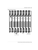
Страница 68: ...n installing cards Note When you install a CMBC card connect at least one Base Station to it before you power on the system to prevent a Config ambiguous alarm The cards must all reside on a single IPE Module The cards must be grouped in adjacent slots on the IPE Module or IPE slots on the CE PE Module The CMCC can be installed anywhere on the IPE Module but it must be located to the left of the o...

Страница 69: ... All Companion cards are equipped with a card status LED The CMCC is also equipped with a system LED labelled SP system processor The card LED is the top LED on the CMCC and the only LED on the expansion cards It is not labeled on any cards If the LED is on the card is out of service and can be safely removed If the LED is off the card is in service and should not be removed The difference between...

Страница 70: ...ontroller software Its state affects the state of all other cards When the CMCC is first installed the system LED does the following Does not flash but remains on for approximately 5 seconds Goes off for approximately 5 seconds Begins flashing to indicate that connected cards and TCM devices are initializing If this normal pattern on off flashing does not occur refer to Normal card LED behavior on...

Страница 71: ...ds appear on the IPE Module in Option 21 through Option 81 systems Figure 24 IPE Module Meridian Companion possible placement of cards Intelligent Peripheral Equipment Superloop Shelf IPE IPE Module IPE Module PE pwr sup Rng gen NT8D01 Controller Card 0 2 3 4 5 6 7 Cont 9 11 12 13 15 1 8 14 10 CMCC CMRCs CMLCs CMBCs CMRCs CMLCs CMBCs ...

Страница 72: ...PE Module Figure 25 CE PE Module Meridian Companion possible placement of cards Common Peripheral Equipment CE PE Module CE PE Module CE PE pwr sup 1 2 3 4 5 6 7 8 9 10 0 1 2 3 4 5 6 7 8 9 FDI CPU Mem SLP 0 SLP 4 SLP 8 SLP 12 SLP 16 SLP 20 Net DTR CPU Mem Net IPE QPC742 FDI NTND01 ICM or QPC687 CPU NTND02 MSPS or NT8D19 MMPS NT8D17 Conf TDS NT8D18 Network DTR network type cards CMCC CMRCs CMLCs CM...

Страница 73: ...expansion cabinet as shown in Figure 27 Option 11 systems that are not using Meridian Mail can also install a Companion card in slot 10 The illustrations indicate the kinds of cards that can be included in the Option 11 system Figure 26 Option 11 Meridian Companion card configuration Main cabinet Pwr Sup 0 1 2 3 4 5 6 7 8 9 10 CPU MM2 CMRCs CMLCs CMBCs Meridian Mail power supply NTAK04 AC DC or NT...

Страница 74: ...g the hardware 553 3601 200 Standard 7 00 November 1998 Figure 27 Option 11 Meridian Companion card configuration Expansion cabinet Pwr Sup 11 12 13 14 15 16 17 18 19 20 CMRCs CMLCs CMBCs NTAK04 AC DC or NTAK05 DC power supply ...

Страница 75: ...e sure the red wire is at the bottom of the cable The cable is polarized to guard against incorrect insertion b Insert the J2 right cable plug into connector J1 left on the card on the far right c Insert the J1 left cable plug into connector J2 right of the next card d Insert the J2 plug of the next cable harness into connector J1 of the next card e Use a blunt object to press the cable plug and t...

Страница 76: ...be located to the left of any CMRC CMLC or CMBC 7 Connect the J1 plug of the last faceplate cable to the CMCC and verify appropriate card LED behavior as described in Normal LED behavior upon installation on page 59 Figure 29 illustrates how the system looks after you have installed cards and interboard faceplate cable harnesses front faceplate LEDs backplane connectors J2 P2 connector CMCC compon...

Страница 77: ...llation and Maintenance Guide Figure 29 Example of cards base station card CMCC SP CMRC radio line card CMRC radio line card CMLC line card CMLC line card CMLC line card CMBC base station card ribbon cable socket for connection of maintenance cable CMBC Controller ...

Страница 78: ...Page 68 of 220 Installing the hardware 553 3601 200 Standard 7 00 November 1998 ...

Страница 79: ...f display does not show System coldstart see Memory Reset on page 70 After performing a Memory Reset the display shows System startup Did you install more Base Stations New installations may require a Base Station software update The system will begin downloading the software to the Base Stations if required Note If you are upgrading an existing system or you have added Base Stations you may see t...

Страница 80: ... is a new system Proceed with programming as described on page 73 is a previously initialized system Apply UTAM Activation Codes Portable Credit Codes and any UTAM Recovery Codes You will also require a new UTAM Recovery Code before the system can be brought online see Activating a disabled system on page 150 UTAM test failed See Table 42 on page 183 Config Ambiguous contains CMBC Ensure a Base St...

Страница 81: ...emove and reinsert the CMCC to prepare for Memory Reset Performing Memory Reset 1 Press ƒ then The display shows Password 2 Enter the Installer password The default password is If the password is correct the display shows Erase all data If the password is incorrect the display shows Password Press RETRY and enter the password again 3 Press YES to reset the memory The display shows Defaults applied...

Страница 82: ...Page 72 of 220 System initialization 553 3601 200 Standard 7 00 November 1998 ...

Страница 83: ...gram the telephony data parameters program mobility data program the Base Station radios that have an external antenna set the time and date set passwords For information about using Companion Manager to program a Meridian Companion system refer to Companion Manager Installation and Operations Guide Before programming a Meridian Companion system see Verifying a Meridian Companion installation on p...

Страница 84: ...eridian Companion system ƒ Use the Feature button to begin a programming session on the Administration Terminal Use the Release button to end a programming session on the Administration Terminal Display buttons The Administration Terminal has three display buttons directly below the display During feature operation or programming these display buttons provide options relating to the top line of te...

Страница 85: ...r º appears in the window beside it The navigation buttons are arranged as follows If the navigation buttons on your Administration Terminal do not correspond to the above arrangement remove the button caps and place them on the correct buttons The buttons below the navigation buttons are not used and have been disabled Figure 30 Administration Terminal up a level ª º down a level back ª º next Fe...

Страница 86: ...st level you prefer Entering a Configuration programming session 1 Press ƒ 2 Enter the Installer password The default password is see Changing passwords on page 88 If the password is correct the display shows A Configuration If the password is incorrect the display shows Password Press RETRY and enter the password again By using the arrow keys you can select a programming category and find the app...

Страница 87: ...the display of the Administration Terminal when the Meridian Companion system generates an alarm Your Meridian Companion supplier can interpret these messages to detect problems affecting system operation The Administration Terminal must be connected to port 00 on the Controller to receive alarm messages This is an example of an alarm message See Table 42 on page 183 for other alarm messages If an...

Страница 88: ...ollowed by the card type CMCC CMRC CMLC or CMBC 6 Press STATE 7 Press to search through all slots verifying that all cards are idle as described in Card Status on page 130 8 Follow diagnostic procedures as necessary Note The CMBC must have at least one powered Base Station connected for the system to recognize it Verifying Base Station status Before performing any programming it is important to ve...

Страница 89: ...git device port number and the device type BS 1 Base Station RAD or 7310 M7310 Administration Terminal 6 Press STATE All BS 1s should be in the Maint state 7 Search through TCM devices by pressing The display should reflect the maintenance state If it does not refer to Troubleshooting a Base Station on page 177 Programming telephony data Adjust telephony defaults only if instructed to do so via a ...

Страница 90: ...r press to continue setting telephony data B03 gain value modification The Meridian Companion system contains digital interconnections that establish various digital signal paths within the system There are currently five paths PBX Meridian 1 to CPP Cordless Portable Part CPP Cordless Portable Part to PBX Meridian 1 PBX Meridian 1 to RAD RAD to PBX Meridian 1 TONE DTMF signal generator to PBX Meri...

Страница 91: ... digits appear without decimal points Press BKSP to make corrections Press OK when you have entered the value 8 Press to search for the next signal path 9 Press to exit or press to continue setting programming features Portable telephone side tone This option enables you can hear your own voice when using the portable or disables you cannot hear your own voice when using the portable the side tone...

Страница 92: ...t value If an adjustment is required upon reset the offset is applied to each card slot address as the cards come online Changing the CMCC slot address 1 Press ƒ and enter the Installer password 2 From A Configuration press The display shows 1 Telephony Data 3 Press then until the display shows CMCC slot followed by the slot address 4 Press to continue in telephony data if the card address is corr...

Страница 93: ...less terminals per card is displayed either 16 WTN or 32 WTN 5 Press APPLY when the correct number of wireless terminals per card is displayed The display shows Warm Reset 6 Press RESET to save the change and begin a warm reset CANCEL does not save any of the changes and does not initiate a warm reset Programming mobility data By default the system has no radios assigned to any cells upon installa...

Страница 94: ...staller password 2 From A Configuration press The display shows 1 Telephony data 3 Press The display shows 2 Mobility Data 4 Press then until the display shows Radios 5 Press The display shows Radio credits 6 Press The display shows Show radio 7 Enter the five digit number of the radio you wish to program The display shows Cell Assignment 8 Press The display shows Antenna Type 9 Press The display ...

Страница 95: ...thout changing slots on their portable telephones All systems must be set to the same LID Two systems that are located near each other were accidentally assigned the same LID users of one system can access the other system This highly unlikely situation could occur for example in an office building occupied by multiple organizations 1 Press ƒ and enter the Installer password 2 From A Configuration...

Страница 96: ...t steps 6 and 7 until four characters have been entered To correct a character press or to move the cursor to the desired position then repeat step 6 9 Press OK If the LID entered is valid the display shows LID changed then System LID followed by the new System LID If the LID entered is not valid the display shows LID not changed Go back to step 5 and repeat the process 10 Record the new LID in Me...

Страница 97: ... is also necessary to reprogram the time and other settings if the CMCC has been powered down for maintenance or for any other reason Programming the system time 1 Press ƒ and enter the Administration password The display shows 1 Registration 2 Press until the display shows 3 Time and Date 3 Press The display shows Time and the current setting 4 Press CHANGE The display shows Hour If you do not wa...

Страница 98: ...ge the year go to step 8 6 Press CHANGE The display shows Year 7 Enter the last two digits of the year 8 Press The display shows Month If you do not want to change the month go to step 11 9 Press CHANGE The display shows Month 10 Enter the month as one or two digits 11 Press The display shows Day If you do not want to change the day go to step 14 12 Press CHANGE The display shows Day 13 Enter the ...

Страница 99: ...Installer password Use BKSP to correct your entry if necessary 7 Press OK The display shows Re enter If you do not enter any digits and press OK the display shows Pswd not changed 8 Reenter the digits and press OK The display shows Password changed ATTENTION You should change the Installer password after the system is installed to protect the integrity of the settings To prevent unauthorized acces...

Страница 100: ...play shows Password 2 Enter the Administration password The display shows 1 Registration 3 Press until the display shows 4 Passwords 4 Press The display shows Admin password 5 Press CHANGE The display shows New pswd 6 Enter up to six digits for the new password Use BKSP for corrections ATTENTION You should change the Administration password after the system is installed to protect the integrity of...

Страница 101: ...ssfully register it with the Companion system The default password is fl or ÂÅÎÈØ but you should set your own password You can choose any combination of one to six digits You will find it easier to remember the password if the numbers correspond to a word 1 Press ƒ The display shows Password 2 Enter the Administration password The display shows 1 Registration 3 Press until the display shows 4 Pass...

Страница 102: ...Note If you do not enter any digits and press OK the display shows Pswd not changed 9 Reenter the digits and press OK The display shows Password changed If the display shows Pswd not changed you did not enter the same password again Go back to step 6 10 Record the new Registration password in Meridian Companion Programming and Provisioning Record 11 Press to exit or press to continue in Administra...

Страница 103: ... control user capacity and to ensure system location verification Codes and credits There are two types of codes associated with a new system activation Each 24 digit code which comes in three eight digit parts is unique to a Meridian Companion System Security Number SSN Portable Credit Code Portable Credit Codes predefine the maximum number of portables that can be registered to the system System...

Страница 104: ...options and descriptions You require codes when initially installing wireless equipment or relocating wireless equipment Companion ID The Companion ID is required to obtain activation codes and credits This number is located on the packing slip and on the labels packaged with the software cartridge You should record this number in Meridian Companion Programming and Provisioning Record System Secur...

Страница 105: ...th codes are retrieved 2 Upgrade you require additional codes to increase the size of a system You may require UTAM Activation Codes Portable Credit Codes or both Upgrade codes are not released until there is an approved purchase order 3 Regression the system s original SSN has changed The regression code is used to change a new SSN back to the original See Troubleshooting portable telephone probl...

Страница 106: ...e Center at 1 800 321 2649 to retrieve the codes Record the Portable Credit Code and the UTAM Activation Code on the UTAM Activation and Portable Credit Codes table in the Meridian Companion Programming and Provisioning Record 6 Press The display shows Codes 7 Press The display shows Code 1 Enter the first eight digit number of the Portable Credit Code and press OK 8 The display shows Code 2 Enter...

Страница 107: ...ion and the display will show Re Eval in prog Radios left nnn Re Eval complete System online as the reevaluation runs its course If the display shows something different see Table 42 on page 183 for troubleshooting tips Note If the UTAM Activation Code entry is unsuccessful the display shows Invalid code If this happens reenter the code or call Nortel Customer Response Center 1 800 321 2649 for as...

Страница 108: ...Page 98 of 220 Activating wireless communications 553 3601 200 Standard 7 00 November 1998 ...

Страница 109: ...ssignments and transcribe these onto the floor plan see Figure 31 on page 100 See the procedure on page 101 Register a test portable see Registering and verifying portable telephones on page 119 Enable the RSSI measurement feature Refer to Meridian Companion Portable Telephone Registration Instructions for additional information Note If you cannot establish a connection with a given radio see Trou...

Страница 110: ...yed as negative values The smaller the negative value the stronger the signal strength For example a signal strength of 60 dBm is stronger than one of 73 dBm If a significant area within the coverage area has an RSSI signal strength less than the cell boundary value refer to Meridian Companion Site Planning Reference Manual to redeploy cell centers in the impacted area to fill the gap or add an ad...

Страница 111: ...lan and the site has not changed since the site deployment 1 Enter Configuration programming 2 Press The display shows 1 Telephony Data 3 Press The display shows 2 Mobility Data 4 Press then until the display shows Cells ATTENTION If there is a serious deployment problem call Northern Telecom Customer Response Center at 1 800 321 2649 to verify that you have approval from UTAM Inc when initially i...

Страница 112: ...ntifying a radio s cell assignment To identify a radio s cell assignment 1 Enter Configuration programming 2 Press then until the display shows 2 Mobility Data 3 Press The display shows Re Evaluation 4 Press The display shows Radios 5 Press The display shows Radio credits 6 Press The display shows Show radio 7 Enter the five digit number of the radio you want to examine The display shows Cell Assi...

Страница 113: ...Meridian Companion portable telephones 1 Verify the card status of the Meridian 1 system 2 Change the ringer default using Table 15 The ringer default determines the maximum number of telephones that can be in the ringing state at the same time For analog phones change the ringer default from 8 to 16 to ensure that portable telephones ring when receiving incoming calls Table 15 LD 97 Changing the ...

Страница 114: ...ase 20B software can be used to print a listing of Meridian Companion wireless terminal numbers WTNs and LD 95 can be used to change create or remove the Call Party Name Display CPND name Each portable telephone can have its own business features and class of service All portable telephones have access to 2500 set features available to wired users For information on implementing features refer to ...

Страница 115: ...ian 1 system package 240 must be installed and enabled and WRLS set to YES If package 240 is not enabled the WRLS prompt does not appear CNDA CNDD and MCRA MCRD cannot be accepted as values for CLS and Table 16 LD 10 X11 release 15 or greater without package 240 Configuring a TN for a portable Prompt Response Meaning REQ NEW new telephone TYPE 500 telephone type TN l s c u Opt 21 81 l u Opt 11 ter...

Страница 116: ...e bolded in Table 17 Table 17 LD 10 X11 release 20B or greater with package 240 Configuring a WTN for a portable Prompt Response Meaning REQ NEW new telephone TYPE 500 telephone type TN l s c u Opt 21 81 l u Opt 11 terminal number CDEN 4D quadruple density DES d d FCC telephone designator CUST 0 99 customer number WRLS YES NO indicates that the TN corresponds to a portable telephone CLID is enable...

Страница 117: ...11 releases 15 or greater without package 240 Printing values Prompt Response Meaning REQ PRT to print information TYPE 500 telephone type TN l s c u terminal number Table 19 LD 20 X11 release 20B with package 240 Printing new values Prompt Response Meaning REQ PRT to print information TYPE 500 telephone type TN l s c u terminal number WRLS YES NO indicates that the TN corresponds to a portable te...

Страница 118: ...ers or Terminal Number Blocks Table 20 LD 81 X11 release 20B with package 240 Printing features and station Prompt Response Meaning REQ LST CNT list or count CUST 0 99 0 99 one customer or range of customers DES d d FCC telephone designator FEAT CNDA CNDD MRCA MCRD WRLS sets with the selected features will be printed or counted Table 21 LD 83 X11 release 20B with package 240 Printing TN and TNB Pr...

Страница 119: ...mer number DIG 0 2045 0 99 existing Dial Intercom Group and member number DN xxxx existing DN of eligible type DCNO 0 254 IDC conversation table number Table 23 LD 95 X11 release 19 or later Adding changing or deleting a CPND Prompt Response Meaning REQ NEW CHG OUT add change or delete a name TYPE NAME CPND name CUST 0 99 customer number DIG 0 2045 0 99 existing Dial Intercom Group and member numb...

Страница 120: ...ian Companion cards Table 24 LD 73 X11 release 20B Defining changing or printing a data block Prompt Response Meaning REQ NEW CHG PRT New change or print TYPE PRI2 PRI PRI data block FEAT PAD Pad category PDCA 1 16 Pad category table BRIT Rx Tx BRI trunk WRLS Rx Tx Meridian Companion R Receive T Transmit x pad value 0 26 Table 25 Card Capacity Cards With MC32 Prior to MC32 CMCC 32 Users 16 Base St...

Страница 121: ...hone TYPE 500 telephone type TN l s c u Opt 21 81 l u Opt 11 terminal number CDEN 4D quadruple density DES d d FCC telephone designator CUST 0 99 customer number WRLS YES NO indicates that the TN corresponds to a portable telephone CLID is enabled as a default MWUN 16 32 changes card density for portable telephones DN x x directory number assigned to the portable CLS CNDA CNDD user can see the nam...

Страница 122: ...ation TYPE 500 telephone type TN l s c u terminal number Table 28 LD 81 X11 release 24 with package 350 Printing TN and TNB Prompt Response Meaning REQ LST TNB prints list of Terminal Numbers or Terminal Number Blocks in designated order CUST x x y cr one customer x range of customer numbers x y all customers cr DES d d FCC telephone designator New information to be printed WRLS YES NO indicates t...

Страница 123: ...Dial Intercom Group and member number DN xxxx existing DN of eligible type DCNO 0 254 IDC conversation table number Table 30 LD 95 X11 release 19 or later Adding changing or deleting a CPND Prompt Response Meaning REQ NEW CHG OUT add change or delete a name TYPE NAME CPND name CUST 0 99 customer number DIG 0 2045 0 99 existing Dial Intercom Group and member number _DISPLAY FMT LAST FIRS display fo...

Страница 124: ... Meaning REQ NEW CHG PRT New change or print TYPE PRI2 PRI PRI data block FEAT PAD Pad category PDCA 1 16 Pad category table BRIT Rx Tx BRI trunk WRLS Rx Tx Meridian Companion R Receive T Transmit x pad value 0 26 MWUN 16 32 changes card density for portable telephones Table 32 LD73 Overlay 10 Error Messages Prompt Meaning SCH0334 wireless and wireline sets have been provisioned on the same line c...

Страница 125: ...ransfer on Radio Loss If a portable telephone user moves beyond radio range or if the battery in the portable telephone becomes weak the call may be dropped To keep calls from terminating abruptly program the system so that it transfers dropped calls to another number There are three values for Transfer on Radio Loss None the default Calls are not transferred Dflt Calls are transferred to the defa...

Страница 126: ...lt number or None 6 Press CHANGE 7 Enter up to 16 digits for the default phone number using 0 to 9 and The will add a two second pause Use BKSP for corrections 8 Press OK to confirm the telephone number The display shows Change Default 9 Press to exit Programming individual Transfer on Radio Loss To program an individual telephone number for transferring a call on radio loss enter an Administratio...

Страница 127: ...hone number using 0 to 9 and The will add a two second pause The DFLT key label appears only if a default telephone number has previously been specified Use BKSP for corrections 8 Press OK to confirm the telephone number The display shows Wccuu followed by the number 9 Press to go to the next WTN Note If OK is pressed and no digits have been entered the telephone number is deleted and Wccuu None a...

Страница 128: ...Page 118 of 220 Programming user options 553 3601 200 Standard 7 00 November 1998 ...

Страница 129: ...Terminal Operations Guide You can use the Administration Terminal to perform the following functions enable registration no portable telephones can be registered unless the system registration is enabled check the status of each WTN deregister a WTN due to portable telephone loss or breakage check to make sure that sufficient credits are available Before a portable will operate it must be register...

Страница 130: ...ates that Master Registration is enabled No is the default and indicates that Master Registration is not enabled Note To prevent interference problems with neighboring systems set the Master Registration to N when the portables are no longer being registered 1 Press ƒ and enter the Administration password The display shows 1 Registration 2 Press The display shows Mstr Reg Enbl followed by the curr...

Страница 131: ...hones Refer to Meridian Companion Portable Telephone Registration Instructions for additional information Verifying a portable telephone s operation After you register a portable you should verify the WTN verify the portable can make or receive calls conduct a signal strength test verify any optional features To verify the WTN 1 Open the portable flap 2 Press Ï The display shows FEATURE LIST 3 Pre...

Страница 132: ...y different from the others Note An RSSI value of 35 dBm is the strongest best possible signal strength As the signal fades the absolute value of the RSSI number increases The link drops as the value approaches 100 dBm Optional checks If Transfer on Radio Loss has been programmed verify that it is operating properly 1 From another telephone make a call to the portable telephone 2 Remove the batter...

Страница 133: ...ct Note 1 Initially the Total credits will equal the Available credits since you have not yet registered any of the portables As you register each portable to the system the number of available Portable Credits decreases by one Note 2 If the total number of Portable Credits is not enough for the system you may need to obtain additional credits Deregistering the WTN Refer to Meridian Companion Admi...

Страница 134: ...Page 124 of 220 Registering and verifying portable telephones 553 3601 200 Standard 7 00 November 1998 ...

Страница 135: ...eridian Companion Administration Terminal system failures exceptions alarm and event descriptions and actions hardware maintenance actions Using maintenance commands A number of commands in LD 32 can be used to examine Meridian Companion from the perspective of the Meridian 1 system The Meridian Companion Administration Terminal can be used to examine the Meridian Companion system components to de...

Страница 136: ...s c shows status indicates status of specified card STAT l s c u shows status indicates status of specified unit ENLC l s c enables card enables the specified card ENLL loop enables loop enables network loop ENLN loop enables card enables network card with specified loop ENLS l s enables shelf enables specified shelf ENLU l s c u enables unit specified unit enabled DISC l s c disables card removes...

Страница 137: ... display shows C Maintenance Six features can be accessed at this point See the following section for a description of each 4 To end a session press To access maintenance functions through Companion Manager refer to Companion Manager Installation and Operations Guide Maintenance features There are six features in the maintenance menu system status card status WTN status TCM status Event Alarm log ...

Страница 138: ...nfiguration press until the display shows C Maintenance 3 Press The display shows 1 System Status 4 Press The display shows the product name MC and protocol PCI 5 Press STATE to see the operational state of the system described in Table 34 6 Press TYPE at any point to reset the display to show the product name and protocol as indicated in step 4 7 Press to see the software version and release numb...

Страница 139: ...YPE Busy system is in use to see the number of busy WTNs then to see the number of TCM devices DSBL or TYPE Wait Idle All idle WTNs and TCM devices have been disabled active WTNs and TCM devices will be disabled as soon as calls terminate DSBL to disable immediately to see the number of busy WTNs then to see the number of TCM devices otherwise TYPE Dsbl Sys All system WTNs and TCM devices have bee...

Страница 140: ...Cnn followed by the card type CMCC CMRC CMLC or CMBC 6 Press to see the firmware version of the current card 7 Press STATE to see the card state described in Table 35 Note Pressing TYPE at any point resets the display to show the card number and type as indicated in step 5 8 Press and to view other cards 9 Press to exit or to continue in Maintenance programming Note The card can be disabled if the...

Страница 141: ...ears only if the slot is empty during a disable enable process DSBL Busy card is in use to see the number of busy WTNs then to see the number of TCM devices DSBL or TYPE Wait Idle All idle WTNs and TCM devices are immediately disabled remaining WTNs and TCM devices will be disabled as soon as calls terminate DSBL to disable immediately to see the number of busy WTNs then to see the number of TCM d...

Страница 142: ...rom A Configuration press until the display shows C Maintenance 3 Press then press until the display shows 3 WTN Status 4 Press Enter the WTN 5 You can enter a number or press to see the first WTN The display shows W followed by the four digit WTN and the WTN type 6 Press STATE to see the WTN state as shown in Table 36 Note Pressing TYPE at any point resets the display so it shows the card number ...

Страница 143: ...t card level Busy The WTN is in use TYPE Wait Idle The card has been disabled when idle This WTN still has an active call It will be disabled as soon as the call terminates handle at card level Maint The WTN has been disabled from the Meridian 1 side After the Meridian 1 system enables the WTN the state becomes Idle or Busy Dsbl User All WTNs have been disabled by user handle at card level Dsbl Sy...

Страница 144: ...f the TCM device has associated software or firmware you can press to see the version of the software firmware If there is no software firmware the button does not appear 7 Press STATE to see the TCM device state as shown in Table 37 The TCM device can be disabled if the state is Idle Busy Failed Maint CSC Radio Equipped or Wait Idle Pressing DSBL shows Disable at once on the display You can selec...

Страница 145: ...r type NONE The state becomes Idle or Busy when a TCM device becomes associated with the port number Busy TCM device is in use DSBL or TYPE Wait Idle TCM device will be disabled as soon as current traffic terminates DSBL to disable immediately TYPE Maint TCM device is not in normal operating mode the Base Stations are not configured into cells or they are downloading new software or CDS is running...

Страница 146: ...ceding this number for example S4 may appear in the event message S1 has the lowest priority If the log is full new event messages with a higher severity number replace existing event messages of a lower severity For this reason check event messages at regular intervals and deal with all messages If an event or alarm occurs while you are using the Administration Terminal for programming your sessi...

Страница 147: ...f new log or Start of log 5 Press or to search through alarms and events in the log 6 Press twice to continue in Maintenance programming Checking the most recent alarm 1 Enter the Event Alarm log 2 Press ALARM The display shows an alarm code if there is an uncleared alarm or No current alarm 3 Press EXIT to return to the Event Alarm log or press OK if an alarm message was displayed Checking when a...

Страница 148: ...s the number of consecutive times that the alarm or event occurred then returns to the previous display Erasing the log 1 Enter the Event Alarm log 2 Press ERASE The display shows Erase log 3 Press YES If no new alarms or events have been added since the list was entered the log is erased and the display shows Log is empty then 5 Evnt Alrm Log If new alarms or events have been added since the list...

Страница 149: ...ent message S1 has the lowest priority If the log is full new event messages with a higher severity number replace existing event messages of a lower severity For this reason check event messages at regular intervals and deal with all messages Entering the Administration log 1 Press ƒ and enter the Installer password 2 From A Configuration press until the display shows C Maintenance 3 Press then p...

Страница 150: ...e in Maintenance programming Checking when an event occurred 1 Enter the Administration log 2 Press or to search through the events in the log 3 Press TIME The display shows the date and time that the event last occurred then returns to the previous display Checking the most recent alarm 1 Enter the Administration log 2 Press ALARM The display shows an alarm code if there is an uncleared alarm or ...

Страница 151: ...essages The alarm messages are displayed on the Administration Terminal This is an example of an alarm message Report the alarm and the time it occurred to your installer or distributor Responding to an alarm code Alarm codes can take up to two minutes to be displayed on the Administration Terminal If the system was turned off when the failure occurred the alarm code appears two minutes after the ...

Страница 152: ...mind If the system detects the need for System Reevaluation you will see Re Eval required or Re Eval recommended on the Administration Terminal If reevaluation is recommended and not required you can clear the message if the system is unchanged for example if a faulty Base Station has been replaced If Re Eval recommended is displayed it could be for the following two reasons a Base Station had los...

Страница 153: ... Telephony Data 3 Press The display shows 2 Mobility Data 4 Press The display shows Re Evaluation 5 Press The display shows Re Eval status 6 Press The display shows one of the following ATTENTION System Reevaluation must be performed for the new configuration to take effect ATTENTION If you modify the Base Station configuration and repower the system before you execute a System Reevaluation then a...

Страница 154: ...tion continue with step 7 schedule a re evaluation CLEAR to continue without running System Reevaluation Re Eval in prog The Meridian Companion system is currently running System Reevaluation Press to exit and wait for display to show Re Eval complete Re Eval disabled The Meridian Companion system has determined that System Reevaluation is not available at this time because the mobility has been d...

Страница 155: ...e Eval complete when the reevaluation procedure is completed Press CLEAR to clear the message Note 1 You may receive alarm messages during this process see Responding to an alarm code on page 141 for more information Note 2 Base Station download will increase the time by approximately 10 minutes Approximate run times for System Reevaluation are shown in the following table ATTENTION System Reevalu...

Страница 156: ...uled or the display shows Not scheduled If the time and date displayed are correct press three times to continue in Configuration programming To schedule System Reevaluation or change the scheduled time go to step 2 of Setting a scheduled time or date To cancel a scheduled System Reevaluation press CANCEL Setting a scheduled time or date Note The system accepts only a date and time set later than ...

Страница 157: ...HANGE to select AM or PM 4 To schedule the date press The display shows Date followed by the current scheduled date today s date if none scheduled If you do not want to change the scheduled date press four times to continue in Configuration programming You may hear a beep after the first To continue scheduling the date a Press CHANGE The display shows Year followed by the currently scheduled year ...

Страница 158: ...on an Option 21 81 release 24 system with package 350 320 portables on an Option 11 release 24 system with package 350 240 portables on Option 21 through Option 81 systems 160 portables on an Option 11 system Note You must ensure that the system has the required hardware to support the number of portables to be registered To obtain Portable Credits 1 Confirm order 2 Call Northern Telecom Customer ...

Страница 159: ...his happens reenter the code or call Northern Telecom Customer Response Center for assistance 1 800 321 2649 13 Follow the procedure Verifying Portable Credits on page 122 or press to exit Adding Radio Credits Radio Credits must have been ordered before you can proceed with the following procedure To increase the number of Radio Credits assigned to a system you must obtain a UTAM Activation Code f...

Страница 160: ...try Successful then Codes Note If the code entry is unsuccessful the display shows Invalid code If this happens reenter the code or call Northern Telecom Customer Response Center 1 800 321 2649 for assistance 11 Follow the procedure Verifying Radio Credits on page 182 or press to exit Activating a disabled system A disabled wireless system implies that Base Stations and portables are not operation...

Страница 161: ...1 Enter the first code number Use BKSP for corrections 8 Press OK The display shows Code 2 Enter the second code number 9 Press OK The display shows Code 3 Enter the third code number 10 Press OK The display shows Entry successful then Codes A few moments after exiting Configuration programming if the code was entered properly the display should show System online Note If the code entry is unsucce...

Страница 162: ...tion no portable registration information is lost After a short initialization sequence the Base Station will be disabled and System Reevaluation will be required to make the Base Station operational and include it into the configuration The following instructions describe how to add or move a Base Station The first eight steps apply only to moving a Base Station If a Base Station is being added b...

Страница 163: ...s being moved reenable previously disabled TCM devices as discussed in TCM Status on page 134 14 If you have moved a Base Station perform System Reevaluation If you have added a Base Station to an existing cell perform a manual re evaluation 15 Note configuration changes in Meridian Companion Programming and Provisioning Record Replacing a defective Base Station To replace a Base Station you do no...

Страница 164: ...Adding expansion cards Add CMRCs CMLCs or CMBCs to the system if existing cards cannot accommodate additional Base Stations or portable telephones Expansion cards can be added to a live system as long as existing cards and faceplate cables are undisturbed Alternatively the entire system can be disabled during installation New cards must be added to the right of an existing system If there is no sp...

Страница 165: ...s from right to left as described in Installing Meridian Companion cards on page 58 The LEDs on the cards should come on immediately flash three times then remain on 3 Faceplate cabling should be installed from right to left with the last cable connecting the new card set to the live system The SP LED on the CMCC card will begin flashing The card LEDs should go out about 20 seconds apart 4 If a ca...

Страница 166: ...ce CMRCs or CMLCs at the right hand end of the system with CMBC cards to expand a system Whereas normally this type of card configuration change would cause an exception condition see Config failure Nonrecoverable inconsistency on page 169 the change can be accomplished using the following procedure The following procedure outlines the process for replacing CMRC or CMLC cards with CMBC cards 1 Per...

Страница 167: ... the corresponding program data relocation on the Meridian 1 and reregister de registered portables to the 16 31 WTN range on the expanded cards Relocating the system When new cards are added it may be necessary to relocate the existing system within the same IPE Module that is shifting the cards to the left to accommodate new cards or to another module The following procedure applies to either ca...

Страница 168: ...inal order 10 Install faceplate cables from right to left so the last connection is made between the CMCC and the card to its right When the connection to the CMCC occurs the system LED will resume flashing as the system begins to initialize the expansion cards The card LED may turn off then turn on as initialization progresses When the system LED stops flashing and stays on the initialization is ...

Страница 169: ...e and the cards are occupying exactly the same slots as in the previous module No action is required proceed to step 18 c The configuration failure message indicates that the cards have not been installed correctly that is in their original order Repeat steps 9 through 12 14 After pressing RESUME you will see System startup followed by System online If the message UTAM test failed is displayed che...

Страница 170: ... the system time and date on page 87 18 Verify proper operation by placing a call to at least one portable telephone on each card Replacing a defective expansion card Troubleshooting cards on page 173 lists the signs that indicate the need for a card replacement Card replacement should be performed when the card is idle If the defective expansion card is on the far right of the Meridian Companion ...

Страница 171: ...MLC use the same maintenance cable 5 Lifting the faceplate connectors unplug the faceplate cable harness from J1 and J2 of the defective card 6 Remove the defective card 7 Replace the defective card with a new card 8 Attach the faceplate cables to the new card 9 Remove the maintenance cable as shown in Figure 32 Maintenance cable on page 163 10 Reenable the card from the Meridian 1 system and the ...

Страница 172: ...t angled connector mate P2 7 Slide the new ROM card into the right angled connector mate P2 on the CMCC 8 Screw the new ROM card securely to the standoffs 9 Reinstall the CMCC and reconnect faceplate cables 10 Verify appropriate LED activity The Meridian 1 system indicates that card polling is reestablished with the XMI002 LoopShelfCard Wait for the system LED on the CMCC to stop flashing 11 Use t...

Страница 173: ...ntenance Guide Figure 32 Maintenance cable base station card CMCC SP CMRC radio line card CMRC radio line card CMLC line card CMLC line card CMLC line card CMBC base station card ribbon cable socket for connection of maintenance cable CMBC card to be removed Controller ...

Страница 174: ...ove the ROM from the defective CMCC 6 Install the ROM on the new CMCC 7 Install the new CMCC into the slot 8 Reconnect the faceplate connector 9 Reprogram the system as described in Programming the Meridian Companion system on page 73 or if you have Companion Manager installed perform a restore operation 10 Reenable the cards on the Meridian 1 side Replacing a defective remote power interconnect u...

Страница 175: ... the TCM ports associated with the RPI using the instructions in TCM Status on page 134 13 Perform reevaluation if necessary Replacing an RPI power unit If the problem appears to be related to the power supply unit follow these instructions 1 Perform an orderly shutdown of the TCM ports associated with the RPI using the instructions in TCM Status on page 134 2 Unplug the RPI power cord from the AC...

Страница 176: ...tem may be defective To replace the defective terminal disconnect its telephone cord then install a new terminal using the instructions in Installing a Companion Administration Terminal on page 41 Portable To replace a portable 1 Deregister the portable from all systems to which it is registered Note If the portable is deregistered outside the range of a system it is necessary to perform deregistr...

Страница 177: ...omer Response Center 1 800 321 2649 to request a Regression Code You will need to provide them with the original and new SSNs Companion ID and site zip code 4 Note the Regression Code Note Do not record this code in the Programming Record A Regression Code cannot be reused 5 To enter the Regression Code a Press ƒ then The display shows Password Enter the Installer password b The display shows A Co...

Страница 178: ... exceptions An exception during system initialization or operation can disable the system except for the Administration Terminal dropping all calls As the system enters a disabled state the Administration Terminal displays an exception message preempting any existing alarm message The three defined Meridian Companion abnormalities listed below relate to configuration inconsistencies and are descri...

Страница 179: ...verable inconsistency can occur during startup or during operation when the system determines that the cards are in a different order from the configuration stored in memory Card type order has not been preserved making portable telephone registration data and system configuration data invalid This can occur if a previously programmed CMCC has been moved to another Meridian 1 system with a differe...

Страница 180: ...erased Config ambiguous The Config ambiguous alarm occurs because there is one or more empty slots between cards a known module has not reported a location the system cannot identify a CMBC without at least one powered Base Station connected to it the system cannot identify a CMBC to the right of another CMBC that does not have at least one powered Base Station connected to it Correct the problem ...

Страница 181: ...w a feature is being used A problem may have been reported because of a misunderstanding about how a feature works Confirm that the person who reported the problem understands the intended use and operation of all features in question 3 Check that you can access host switch features from the Meridian Companion system To verify if the access lines have been programmed correctly try the host switch ...

Страница 182: ...you can make and receive calls from various portables If there is no wireless activity you may require a UTAM Activation Code a UTAM Recovery Code or a Regression Code from Northern Telecom Customer Response Center 1 800 321 2649 8 Verify connection For each cell center in the system verify that you can establish a connection with all the radios at that cell center To identify a radio s cell see I...

Страница 183: ...cards using visual inspection and Meridian Companion maintenance 1 Verify that LEDs are functioning properly as described in Normal card LED behavior on page 174 2 Check the status of the cards as described in Card Status on page 130 3 Disable then enable any suspicious card using the procedure described in Card Status on page 130 4 Repeat as necessary Table 38 Power troubleshooting Symptom Possib...

Страница 184: ...ED flashes to indicate that the cards and any associated TCM devices are initializing after initialization LED turns off unless system detects that the cards are not in the same order as previously recorded a non recoverable inconsistency in which case system is disabled and LED changes from flashing to on until exception is cleared Administration Terminal or Companion Manager user disables system...

Страница 185: ...n Companion enabled disabled Companion system power status LED behavior not connected N A N A powering up remain on after flashing three times being connected enabled N A normal go off quickly already connected enabled N A powering up flash three times go on then go off quickly being connected disabled card and system enabled normal go off slowly being connected disabled system disabled normal rem...

Страница 186: ... 4 Check that the Administration Terminal is connected to the correct port 5 Check the 50 pin connectors at the system and make sure they are plugged in properly 6 Check the 25 pair TCM cables at the distribution frame to make sure they are connected to the right ports 7 Check the telephone wiring connections at the distribution frame to make sure the connections have been made on the appropriate ...

Страница 187: ...ashes for about 15 seconds when a Base Station is powered up This is normal If the red LED continues to flash then one of the following problems may exist The Base Station is not connected to the Controller or line card The wiring to the Base Station is not correct Check for open circuits through the secondary protectors for applications with exposed wiring The two way DC loop resistance of the po...

Страница 188: ...missing Troubleshooting a remote power interconnect unit Multiple Base Station malfunctions usually indicate an RPI problem 1 Verify that the card associated with the RPI is properly engaged in its slot 2 Verify the Base Stations a Check to see that the green light is on b Check to see that the red light is not solid A solid red light indicates that both radios on the Base Station are busy the sys...

Страница 189: ...that all connections to the RPI power cord jumper lead input and output etc are correct and secured 4 Check that the UPS fuse is live a Remove the RPI cover b Unplug the RPI from the AC outlet c Remove the fuse cover d Visually inspect the fuse to see if it needs replacement e Replace the fuse if necessary 5 Make sure the TCM device wiring has been correctly installed 6 If none of the Base Station...

Страница 190: ...hone if any is idle If no dial tone is present the portable might not be registered Verify that the system has available Portable Credits and try to register the portable again If the number of available Portable Credits is 0 then you will need to obtain additional credits before you can register the portable see Adding Portable Credits on page 148 4 On a portable press Ï The display shows FEATURE...

Страница 191: ...l tone telephones are MADN and the other telephone is off hook Meridian 1 programming problem WTN is enabled but not configured make sure other telephone is not off hook ask technical support to check that the Meridian 1 system is correctly programmed link is established but there is an overflow tone WTN module from the Companion side is disabled or defective or failed Meridian 1 TN or card is dis...

Страница 192: ...should have If you received the UTAM test failed message verify the number of Base Stations Note 1 The number of Radio Credits must be double the number of Base Stations you have installed Refer to Meridian Companion Programming and Provisioning Record to determine the number of Base Stations Each Base Station has two radios so each Base Station requires two credits Note 2 As each Base Station is ...

Страница 193: ...stem check all the wiring associated with these TCM devices Alarm 11 The internal circuitry has failed The CMCC is defective Replace the CMCC follow the instructions on page 164 Alarm 23 xx Cell xx is out of service because there are no operational radios in that cell This alarm occurs only at the end of System Reevaluation During the last step of reevaluation or after a system restart as the syst...

Страница 194: ...51 If all the Base Stations you expected to see are not showing or they are in a failed state check that the TCM wiring of Base Stations is correct that there is power to the Base Stations and RPIs or plug top power supplies that the location and number of Base Stations are correct that any Base Station Modules are properly connected to the expansion ports 2 Once you have corrected the problem run...

Страница 195: ...2 WTNs for MC32 feature with package 350 on CMRC or CMLC have been disconnected from the system for at least 1 minute or CMRC CMLC or CMBC cc which was restarted more than 3 minutes ago is still not operational The CMRC has been disconnected from the IPE Module slot Reconnect the CMRC A faceplate cable in the chain between the CMCC and this CMRC or CMLC has been disconnected or loosened from its c...

Страница 196: ... coldstart A nonrecoverable NVRAM corruption was detected during restart A cold start occurs automatically This message appears only at power up This is normal for a new installation If this occurs on repowering an existing system it means that the system has lost its memory Reprogram the system using the programming record Reregister all portable telephones Re Eval required The Meridian Companion...

Страница 197: ...valuation schedule a reevaluation CLEAR the message and continue without running System Reevaluation UTAM code req d The wireless system is disabled This is normal for a new installation Follow the procedures described in Activating wireless communications on page 93 The only other time this alarm should appear is if you are rebuilding a system 1 Enter a UTAM Activation Code See Activating a new s...

Страница 198: ...Maintenance 2 Check that there is power to the Base Stations and RPI or plug top power supply that the location and number of Base Stations are correct that there are at least four cells in the system configuration all connections to the CCMC that there are sufficient Radio Credits to support the number of Base Stations you have connected 3 Restart the system with the correct system configuration ...

Страница 199: ... and available number of radio credits using the Administration Terminal 2 Remove the excess Base Stations and restart the system To determine the number of connected Base Stations to remove subtract the total number of radio credits from the total number of connected Base Stations Remember that each Base Station has two radios See Verifying Radio Credits on page 182 If you have increased the numb...

Страница 200: ...ared EVT222 The debugging facility has been accessed EVT299 The system has been restarted after a power outage EVT301 ccuux Radio ccuux cannot successfully receive the data image during download Both radios belonging to the Base Station will be disabled This may occur if the flash EEPROM is faulty The Base Station should be replaced EVT302 ccuux Radio ccuux cannot be written to during data transfe...

Страница 201: ...urs the link is dropped Radio ccuux is returned to service EVT307 ccuux01 An unrecoverable radio fault has occurred Radio ccuux will be disabled and taken out of service If a link is active when this error occurs the link is dropped A corresponding alarm code 53 will occur EVT307 ccuux02 The built in self test on the Base Station has failed Radio ccuux will be disabled and taken out of service If ...

Страница 202: ...t 01091 in this case Table 44 Event messages in the Administration log Event code Meaning EVT220 The Administration log has been cleared EVT 400 The system has been manually restarted EVT 412 The Installer password has been changed The parameter contains the extension number that changed the password EVT 413 The Administration password has been changed The parameter contains the extension number t...

Страница 203: ...as followed its normal recovery from an unusual combination of system events If the same event number keeps appearing and is not described in Table 32 or Table 43 report it to your installer or distributor EVT 434 The Registration password has been changed EVT 440 An invalid software code has been entered EVT 450 Someone has initiated a Companion Manager session Table 44 Event messages in the Admi...

Страница 204: ...Page 194 of 220 Troubleshooting 553 3601 200 Standard 7 00 November 1998 ...

Страница 205: ...ta Dial delay B03 Gain Values Side tone CMCC slot 32 WTN 1 Registration Mstr Reg Enbl WTN Reg Status Show WTN Reg Locked 1 System Status 2 Mobility Data Re Evaluation Re Eval status Re Eval schedule 2 User Options Radio loss hdlng Change Default Dflt Change WTN 2 Card Status Show card Radios Radio credits Show Radio Cell Assignment Antenna Type 3 Time and Date Time Date 3 WTN Status Show WTN ...

Страница 206: ... 1998 Cells Show Cell xxx Cxxx Radios 4 Passwords Admin password Reg password 4 TCM Status Show TCM System LID 5 Evnt Alrm Log 3 Admin set data Installer pswd 6 Admin Log 4 Software codes SSN Codes Table 37 Programming overview continued A Configuration B Administration C Maintenance ...

Страница 207: ...be activated until installation at the system s authorized location is verified and approved by UTAM Inc The system is equipped with an automatic mechanism for disabling wireless operation in the event the system is moved outside the area where its operation has been approved by UTAM Inc This mechanism complies with FCC requirements Registration Each Meridian Companion PCI system is registered wit...

Страница 208: ...ations directly to a CO line interface Doing so may result in equipment damage CAUTION The Meridian Companion Administration Terminal and Base Stations must not be used as off premises equipment Installers should check the lightning surge arrestors at the cable entry point to the building with special attention to the grounding Any problems should be reported to your telephone company in writing B...

Страница 209: ...h the preceding conditions might not prevent degradation of service in some situations Repairs to certified equipment should be made by SHOCK To avoid electrical shock hazard to personnel or equipment damage observe the following precautions when installing telephone equipment Never install telephone wiring during a lightning storm Never install telephone jacks in wet locations unless the jack is ...

Страница 210: ...his equipment cannot be used on public coin phone service provided by the telephone company Telecom compliance The Meridian Companion PCI system meets FCC Part 68 requirements for loop start Central Office interface Telephone company notification You do not need to contact your telephone company before connecting a Meridian Companion PCI system to the telephone network The telephone company howeve...

Страница 211: ...ne company might make changes in its facilities equipment operations or procedures that could affect the correct functioning of your system If the company does you will be notified in advance to give you an opportunity to maintain uninterrupted telephone service In the event of an equipment malfunction all repairs will be performed by Northern Telecom Ltd or one of its authorized dealers Radio Fre...

Страница 212: ... the device to prevent overloading The REN is increased each time a terminal device is connected to the telephone line In most areas the sum of the RENs should not exceed 5 The REN of the system is 1 5 B Repair facility Note for hearing aid users Use of the portable telephone may produce an audible tone within a hearing aid A headset recommended for use with hearing aids can prevent the occurrence...

Страница 213: ...sages The Administration Terminal does not support voice telephony when connected to a Meridian Companion system alarm code A number that appears on the Administration Terminal display informing you of the type of fault the Controller has detected in the system antenna Each Base Station has its own built in antenna External antennae can be used indoors or outdoors to extend radio coverage to hard ...

Страница 214: ...cted to a PC running Companion Manager 15 Base Stations and 16 portable telephones With Feature MC32 CMCC supports the Administration Terminal or a RAD connected to a PC running Companion Manager 15 Base Stations and 32 portable telephones It can be installed in the IPE Module CE PE Module or Option 11 expansion cabinet CMLC Companion Meridian Line Card Supports 16 portable telephones With Feature...

Страница 215: ...or in a remote location and connects to each system through a Remote Access Device RAD Companion Meridian Base Station Card See CMBC Companion Meridian Controller Card See CMCC Companion Meridian Line Card See CMLC Companion Meridian Radio Line Card See CMRC coverage area The area in which a portable user should be able to make and receive calls It can include both indoor and outdoor areas stairwe...

Страница 216: ... primary and secondary protectors external antenna A passive radio frequency receiver connected to a Base Station radio An external antenna can be used instead of the internal Base Station antenna to extend radio coverage to hard to reach places or locations where Base Stations cannot be installed FCC Federal Communications Commission hand off An active radio link to a portable is transferred from...

Страница 217: ...Multiple Call Arrangement Denied MDF See Main Distribution Frame Message Waiting Indicator A visual or audible telephone set indicator that alerts the user to the fact that a message is waiting Multiple Appearance Directory Number MADN A host switch feature that allows the assignment of the same host switch telephone number to any number of lines that are wired to the host switch Multiple Call Arr...

Страница 218: ...stem 160 portables for an Option 11 system portables The Companion portable is a battery powered pocket size portable telephone Meridian Companion can support up to 480 portable telephones depending on card configuration Primary protector A voltage surge protector connected between each line conductor and ground located where telecommunications conductors enter a building structure Programming The...

Страница 219: ...eused restores the previous system security number so that previously applied UTAM Activation Codes and Portable Credit Codes can be reentered to restore full system operation Remote Access Device RAD Allows a PC running Companion Manager or Companion Diagnostic Software to access the Meridian Companion system Access may be established by connecting the RAD on the customer site using a local conne...

Страница 220: ...n administration PC If a system has an Administration Terminal and a RAD each has a separate port The other ports support Base Stations and portable telephones TN Terminal Number A port on a Meridian 1 system to which a particular telephone set is connected UTAM Activation Code Activates the wireless capability on a new system and in system upgrades involving a change to the number of Base Station...

Страница 221: ...g a session 77 entering a password 76 entering a session 76 Master Registration 120 radio loss handling 116 setting the date 88 setting the time 87 system administrator 90 Transfer on Radio loss 116 Administration Terminal alarm messages 77 connection to Controller 77 contrast 76 device 79 dialpad buttons 74 display 74 display buttons 74 displaying system date 88 displaying system time 87 exceptio...

Страница 222: ...em Reevaluation 142 TCM port 79 troubleshooting 177 wiring length 12 Base Station address adding to site plan 101 BIX connector board 28 BNC connectors 38 button caps 75 B03 gain values changing 80 digital signal paths 80 displaying 81 entering a new 81 negative 81 positive 81 telephony data 81 C cabling from Base Station to RPI 27 card LED behavior 175 card status checking card type 130 checking ...

Страница 223: ...105 Meridian 1 system 103 configuring portables with X11 releases 104 contrast adjusting 76 critical point 100 D default Administration password 90 Installer password 88 Registration password 91 default password Administration programming 76 Configuration programming 76 deployment 101 deregistering wireless terminal number WTN 123 device Administration Terminal 79 Base Station 79 RAD 79 dialpad bu...

Страница 224: ...feature codes entering 74 Federal Communications Commission See FCC floor plan cell assignments 100 cell center 100 critical point 100 G generating LID 85 H hand off radio coverage area 99 hardware installing 11 hearing aids and portable telephones 202 high power mode cell boundary value 100 I idle cards 78 initialization 69 initializing the system 69 Installer password changing 88 default 88 reco...

Страница 225: ...us 134 WTN status 132 maintenance session verifying cards 78 Master Registration default 120 disabling 120 enabling 120 MDF wiring 78 Memory Reset entering code 70 erasing system data 71 reinitializing system 70 Meridian 1 card maintenance 126 card status 103 extended features 104 LD 97 103 privacy feature 104 ringer default 103 Meridian 1 system configuring 103 mobility data assigning cells 83 pr...

Страница 226: ...onnector position of 33 programming Feature button 74 Installer 76 mobility data 83 overview 195 Release button 74 system date 88 system time 87 system time and date 87 telephony data 79 the system 73 R RAD device 79 replacing 166 troubleshooting 182 radio cell assignment 102 radio assignments viewing 101 radio coverage and hand off 99 radio credits adding 149 software codes 149 UTAM Activation Co...

Страница 227: ...p 31 replacing 164 troubleshooting 178 upgrading 22 32 wiring 27 RPI configurations large installations 20 small installations 19 RPI power 78 RPI power unit replacing 165 RSSI and cell boundary value 99 observing 99 RSSI measurements 100 S searching using navigation buttons 75 severity number and events 136 139 Show cell viewing cell assignment 102 side tone changing 81 default 81 portable teleph...

Страница 228: ...nsistency 169 recoverable inconsistency 168 system states 129 system time 87 system time and date when to reset 87 T TCM connections and polarity 18 TCM device states 135 TCM port 79 TCM status checking device status 134 checking device types 134 device firmware 134 device software 134 displaying TCM 79 entering device number 134 telephony data B03 gain values 79 81 changing defaults 79 defaults 7...

Страница 229: ...ment 101 disabling 101 wireless terminal number WTN checking status 132 deregistering 123 states 133 verifying 121 wiring an RPI 27 X X11 release 15 18 and CPND 109 113 X11 release 19 and CPND 109 113 X11 release 20B and data blocks 110 114 printing features 108 printing new values 107 printing terminal numbers 108 112 printing values 107 112 X11 releases configuring portables 104 programming opti...

Страница 230: ...Page 220 of 220 Index 553 3601 200 Standard 7 00 November 1998 ...

Страница 231: ......

Страница 232: ...e the information only to its employees with a need to know and shall protect the information in whole or in part from disclosure and dissemination to third parties with the same degree of care it uses to protect its own confidential information but with no less than reasonable care Except as expressly authorized in writing by Nortel Networks the holder is granted no rights to use the information ...

Отзывы: