


10-30
Page 74
2008-10-01
1. SUBMITTAL DESCRIPTIONS
A. INTRODUCTION
(1)
The information found in this section is general in nature and consists of part
numbers, product descriptions and options, dimensions, specifications and
equipment features.
B. NH UNIT
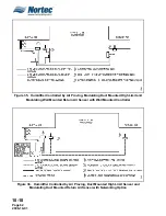
(1)
The different wiring connections to the humidifier unit can be found in Figure 2. All
wiring is to be in accordance with existing national and local electrical codes.
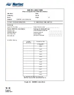
(2)
Performance data for single and double units can be found in Figure 3, Figure 4,
and Figure 5.
(3)
NH Series unit options and common accessories universal are found in Tables 1
and 2.
C. DISTRIBUTORS
(1)
A description of the accessories for the steam distributor can be found in Table 3.
(2)
Dimensions for the steam distributor are found in Figure 6, Figure 7, Figure 8.
D. SAM-e
(1)
This section identifies the dimensions for the various configurations and
components that make up a SAM-e installation.
(2)
General dimensions for the SAM-e and Mini SAM-e are found in Figures 9 and 10.
(3)
For an in-duct/AHU installation without mounting frame refer to Figure 11.
(4)
For an in-duct/AHU installation with mounting frame refer to Figure 12.
(5)
For an outside duct installation without mounting frame refer to Figure 13.
(6)
For an outside duct installation with mounting frame refer to Figure 14.
(7)
For a vertical duct installation refer to Figure 15.
(8)
For outside duct mounting cover plates refer to Figure 16.
(9)
For atmospheric SAM-e adapter dimensions refer to Figure 17.
(10) For atmospheric steam header and adapter configuration refer to Figure 18.
E. BLOWER PACK
(1)
Remote Blower Packs
(a) Remote blower packs are powered from the NH humidifier from a primary
voltage terminal block provided and fed from the leaving side of the unit
contactor to operate blower pack in conjunction with unit operation. A matching
terminal block is incorporated in the blower pack. Field wiring is required
Содержание NHPC
Страница 1: ...2538144 B NH Series NHTC NHPC ELECTRODE STEAM HUMIDIFIER Engineering Manual TM ...
Страница 9: ...10 00 Page 1 2008 10 01 10 00 INTRODUCTION ...
Страница 10: ...10 00 Page 2 2008 10 01 Figure 1 NHTC ...
Страница 13: ...10 00 Page 5 2008 10 01 Figure 2 Optimum Boiling Time Figure 3 Conductivity ...
Страница 18: ...10 00 Page 10 2008 10 01 Figure 6 Typical NHRS Installation Sheet 1 of 2 ...
Страница 19: ...10 00 Page 11 2008 10 01 Figure 7 Typical NHRS Installation Sheet 2 of 2 ...
Страница 20: ...10 10 Page 12 2008 10 01 10 10 HUMIDITY STEAM ABSORPTION AND DISTRIBUTION ...
Страница 35: ...10 10 Page 27 2008 10 01 Figure 2 Psychrometric Chart ...
Страница 47: ...10 10 Page 39 2008 10 01 Figure 13 Humidification Distance Nomogram Figure 12 Cutting Duct For Mounting ...
Страница 58: ...10 10 Page 50 2008 10 01 Figure 26 Typical SAM e Installation for Atmospheric Steam Applications ...
Страница 64: ...10 10 Page 56 2008 10 01 Figure 30 NORTEC OnLine Monitoring ...
Страница 71: ...10 20 Page 63 2008 10 01 10 20 SPECIFICATIONS ...
Страница 81: ...10 30 Page 73 2008 10 01 10 30 SUBMITTALS ...
Страница 86: ...10 30 Page 78 2008 10 01 Figure 2 Primary Line Voltage Wiring to Unit ...
Страница 87: ...10 30 Page 79 2008 10 01 Figure 3 Physical Data NHTC NHPC 005 030 ...
Страница 88: ...10 30 Page 80 2008 10 01 Figure 4 Physical Data NHTC NHPC 050 100 ...
Страница 89: ...10 30 Page 81 2008 10 01 Figure 5 Physical Data NHTC NHPC 150 200 ...
Страница 95: ...10 30 Page 87 2008 10 01 Figure 11 In Duct AHU Installation Without Mounting Frame Installation ...
Страница 96: ...10 30 Page 88 2008 10 01 Figure 12 In Duct AHU Installation With Mounting Frame Installation ...
Страница 97: ...10 30 Page 89 2008 10 01 Figure 13 Outside Duct Installation Without Mounting Frame Installation ...
Страница 98: ...10 30 Page 90 2008 10 01 Figure 13 In Duct AHU Installation With Mounting Frame Installation ...
Страница 99: ...10 30 Page 91 2008 10 01 Figure 14 Vertical Duct Installation Figure 15 Outside Duct Mounting Cover Plates ...
Страница 100: ...10 30 Page 92 2008 10 01 Figure 16 Atmospheric SAM e Adapter Dimensions ...
Страница 101: ...10 30 Page 93 2008 10 01 Figure 17 Atmospheric Steam Header and Adapter Configuration ...
Страница 102: ...10 30 Page 94 2008 10 01 Figure 18 Physical Data for Remote Mounted Blower Pack ...
Страница 103: ...10 30 Page 95 2008 10 01 Figure 19 Physical Data Units with Optional Built On Blower Packs ...
Страница 104: ...10 30 Page 96 2008 10 01 Figure 20 Physical Data Units with Optional Built On Blower Packs ...


