


10-10
Page 41
2008-10-01
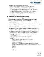
determine the number of steam distributors that must be use for short saturation
distances.
(2) If the ‘Saturation Distance’ for one steam distributor is not sufficient, add more steam
distributors until the minimum saturation distance is attained. (See Figure 13.)
(3) To determine the number of distributors required, complete the following list:
(a) Air humidity after humidification _____ %rh. (A high limit humidistat should be set
at 80 – 85% to prevent wetting of ducts.)
(b) Air temperature before humidification _____.
(c) Air velocity in duct _____ ft/min.
(d) Maximum steam mass flow _____ lbs/hr.
(e) Active zone H of steam distributor _____ in. (See Figure 13.)
NOTE
The manufacturer recommends the appropriate distance modification factors when
filters or humidification sensors are installed downstream. For applications that are
outside of the Nomogram’s range, please consult a NORTEC representative.
G. TYPICAL APPLICATIONS
(1) Representations of typical applications are found in Figure 15 and Figure 16.
H.
DISTRIBUTOR DIMENSIONS
(1) Distributor dimensions for the various distributor models can be found in
Chapter 10-30.
Figure 16. Small Units On Residential
Furnaces
Figure 15. Roof Top Units 2-20 Tons –
Typical Location
Содержание NHPC
Страница 1: ...2538144 B NH Series NHTC NHPC ELECTRODE STEAM HUMIDIFIER Engineering Manual TM ...
Страница 9: ...10 00 Page 1 2008 10 01 10 00 INTRODUCTION ...
Страница 10: ...10 00 Page 2 2008 10 01 Figure 1 NHTC ...
Страница 13: ...10 00 Page 5 2008 10 01 Figure 2 Optimum Boiling Time Figure 3 Conductivity ...
Страница 18: ...10 00 Page 10 2008 10 01 Figure 6 Typical NHRS Installation Sheet 1 of 2 ...
Страница 19: ...10 00 Page 11 2008 10 01 Figure 7 Typical NHRS Installation Sheet 2 of 2 ...
Страница 20: ...10 10 Page 12 2008 10 01 10 10 HUMIDITY STEAM ABSORPTION AND DISTRIBUTION ...
Страница 35: ...10 10 Page 27 2008 10 01 Figure 2 Psychrometric Chart ...
Страница 47: ...10 10 Page 39 2008 10 01 Figure 13 Humidification Distance Nomogram Figure 12 Cutting Duct For Mounting ...
Страница 58: ...10 10 Page 50 2008 10 01 Figure 26 Typical SAM e Installation for Atmospheric Steam Applications ...
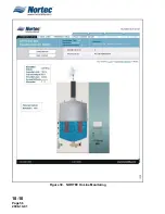
Страница 64: ...10 10 Page 56 2008 10 01 Figure 30 NORTEC OnLine Monitoring ...
Страница 71: ...10 20 Page 63 2008 10 01 10 20 SPECIFICATIONS ...
Страница 81: ...10 30 Page 73 2008 10 01 10 30 SUBMITTALS ...
Страница 86: ...10 30 Page 78 2008 10 01 Figure 2 Primary Line Voltage Wiring to Unit ...
Страница 87: ...10 30 Page 79 2008 10 01 Figure 3 Physical Data NHTC NHPC 005 030 ...
Страница 88: ...10 30 Page 80 2008 10 01 Figure 4 Physical Data NHTC NHPC 050 100 ...
Страница 89: ...10 30 Page 81 2008 10 01 Figure 5 Physical Data NHTC NHPC 150 200 ...
Страница 95: ...10 30 Page 87 2008 10 01 Figure 11 In Duct AHU Installation Without Mounting Frame Installation ...
Страница 96: ...10 30 Page 88 2008 10 01 Figure 12 In Duct AHU Installation With Mounting Frame Installation ...
Страница 97: ...10 30 Page 89 2008 10 01 Figure 13 Outside Duct Installation Without Mounting Frame Installation ...
Страница 98: ...10 30 Page 90 2008 10 01 Figure 13 In Duct AHU Installation With Mounting Frame Installation ...
Страница 99: ...10 30 Page 91 2008 10 01 Figure 14 Vertical Duct Installation Figure 15 Outside Duct Mounting Cover Plates ...
Страница 100: ...10 30 Page 92 2008 10 01 Figure 16 Atmospheric SAM e Adapter Dimensions ...
Страница 101: ...10 30 Page 93 2008 10 01 Figure 17 Atmospheric Steam Header and Adapter Configuration ...
Страница 102: ...10 30 Page 94 2008 10 01 Figure 18 Physical Data for Remote Mounted Blower Pack ...
Страница 103: ...10 30 Page 95 2008 10 01 Figure 19 Physical Data Units with Optional Built On Blower Packs ...
Страница 104: ...10 30 Page 96 2008 10 01 Figure 20 Physical Data Units with Optional Built On Blower Packs ...


