


10-10
Page 34
2008-10-01
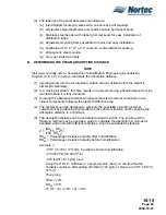
(3) NORTEC recommends the use of insulated hard copper steam lines on distances of
more than 10 feet and no more than 3 elbows (90
⊃
). The use of flexible steam hose on
runs of more than 10 feet can reduce these recommended distances in Table 14 by as
much as 25%. Steam hose can crimp and cause back pressure.
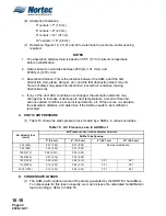
Table 14. Maximum Recommended Length of Steam Runs
(4) Steam lines should slope upwards from the humidifier to the steam distributor. (See
Figure 7.)
(5) Flexible steam hose, if used, must be supported to avoid crimps, bends, and sags.
(Please consult local agent if proper slopes are not available.)
(6) If the steam supply line must be routed below the humidifier location, a condensate trap
‘tee’ will be required to prevent blockage at the low point in the steam line. Run the
condensate hose to the nearest floor drain after trapping. (See Figure 8.)
(7) Long steam runs with improper slopes can produce spitting at the distributor because
the steam is travelling at a high velocity and will push condensate out the distributor. If
a slope of 2" for every 12" of steam run cannot be achieved, then condensate must be
removed before the distributor. (See Figure 4.)
B.
CONDENSATE RETURN
(1) Each steam distributor has a built-in condensate return. (See Figure 9.) Flexible
condensate return hose (available from NORTEC) is recommended for routing
condensate back into the humidifier’s fill cup, or to a drain. A short length of
d
" OD
copper tubing is supplied by NORTEC when routing condensate hose back to the fill
cup. Similarly, a short length of
d
" condensate hose is supplied to serve as a flexible
coupling with field-supplied copper condensate line. Long condensate runs should be
drained to a floor drain to prevent excessive condensate water from entering the
cylinder.
NOTE
Excessively long steam runs (over 20 feet) may require the use of ½" OD condensate
return lines – supplied by others.
Unit Size
Steam Output
Distance
Possible Losses
NH-005
5 lbs/hr
8 feet
1.0 lbs/hr
NH-010
10 lbs/hr
15 feet
1.5 lbs/hr
NH-020
20 lbs/hr
20 feet *
2.0 lbs/hr
NH-030
30 lbs/hr
25 feet *
2.5 lbs/hr
NH-050
50 lbs/hr
40 feet **
4.0 lbs/hr
NH-075
75 lbs/hr
50 feet **
5.0 to 10.0 lbs/hr
NH-100
100 lbs/hr
50 feet **
5.0 to 10.0 lbs/hr
NH-150
150 lbs/hr
50 feet/cylinder **
5.0 to 10.0 lbs/hr
NH-200
200 lbs/hr
50 feet/cylinder **
5.0 to 10.0 lbs/hr
* Use one inch copper steam supply for longer runs.
** Use two inch copper steam supply for longer runs.
NOTES:
1. This table gives the maximum recommended length of steam run by unit size.
2. The use of any steam line other than copper or NORTEC supplied steam hose will void the warranty and
may adversely effect the operation of the humidifier.
Содержание NHPC
Страница 1: ...2538144 B NH Series NHTC NHPC ELECTRODE STEAM HUMIDIFIER Engineering Manual TM ...
Страница 9: ...10 00 Page 1 2008 10 01 10 00 INTRODUCTION ...
Страница 10: ...10 00 Page 2 2008 10 01 Figure 1 NHTC ...
Страница 13: ...10 00 Page 5 2008 10 01 Figure 2 Optimum Boiling Time Figure 3 Conductivity ...
Страница 18: ...10 00 Page 10 2008 10 01 Figure 6 Typical NHRS Installation Sheet 1 of 2 ...
Страница 19: ...10 00 Page 11 2008 10 01 Figure 7 Typical NHRS Installation Sheet 2 of 2 ...
Страница 20: ...10 10 Page 12 2008 10 01 10 10 HUMIDITY STEAM ABSORPTION AND DISTRIBUTION ...
Страница 35: ...10 10 Page 27 2008 10 01 Figure 2 Psychrometric Chart ...
Страница 47: ...10 10 Page 39 2008 10 01 Figure 13 Humidification Distance Nomogram Figure 12 Cutting Duct For Mounting ...
Страница 58: ...10 10 Page 50 2008 10 01 Figure 26 Typical SAM e Installation for Atmospheric Steam Applications ...
Страница 64: ...10 10 Page 56 2008 10 01 Figure 30 NORTEC OnLine Monitoring ...
Страница 71: ...10 20 Page 63 2008 10 01 10 20 SPECIFICATIONS ...
Страница 81: ...10 30 Page 73 2008 10 01 10 30 SUBMITTALS ...
Страница 86: ...10 30 Page 78 2008 10 01 Figure 2 Primary Line Voltage Wiring to Unit ...
Страница 87: ...10 30 Page 79 2008 10 01 Figure 3 Physical Data NHTC NHPC 005 030 ...
Страница 88: ...10 30 Page 80 2008 10 01 Figure 4 Physical Data NHTC NHPC 050 100 ...
Страница 89: ...10 30 Page 81 2008 10 01 Figure 5 Physical Data NHTC NHPC 150 200 ...
Страница 95: ...10 30 Page 87 2008 10 01 Figure 11 In Duct AHU Installation Without Mounting Frame Installation ...
Страница 96: ...10 30 Page 88 2008 10 01 Figure 12 In Duct AHU Installation With Mounting Frame Installation ...
Страница 97: ...10 30 Page 89 2008 10 01 Figure 13 Outside Duct Installation Without Mounting Frame Installation ...
Страница 98: ...10 30 Page 90 2008 10 01 Figure 13 In Duct AHU Installation With Mounting Frame Installation ...
Страница 99: ...10 30 Page 91 2008 10 01 Figure 14 Vertical Duct Installation Figure 15 Outside Duct Mounting Cover Plates ...
Страница 100: ...10 30 Page 92 2008 10 01 Figure 16 Atmospheric SAM e Adapter Dimensions ...
Страница 101: ...10 30 Page 93 2008 10 01 Figure 17 Atmospheric Steam Header and Adapter Configuration ...
Страница 102: ...10 30 Page 94 2008 10 01 Figure 18 Physical Data for Remote Mounted Blower Pack ...
Страница 103: ...10 30 Page 95 2008 10 01 Figure 19 Physical Data Units with Optional Built On Blower Packs ...
Страница 104: ...10 30 Page 96 2008 10 01 Figure 20 Physical Data Units with Optional Built On Blower Packs ...


