


10-20
Page 66
2008-10-01
10 Accepts a signal from BMS/BAS system or modulating humidistat.
11 Single or dual channel signal acceptance.
12 Isolated plumbing and electrical compartment with cabinet made of 18-gauge
powder coat paint finish and 20 gauge plumbing electrical door. Modular
plumbing and electrical fully assembled and pre-wired (no field assembly
required).
13 Removable door (no special tools required) to allow user full front access of
plumbing and electrical sections.
14 Plumbing door interlock safety switch to allow power interruption when
installing or servicing the humidifier.
15 Standard of acceptance NORTEC NHTC Series.
16 C-UL_US listed.
17 Spec
(2) Humidifier Controls (NHTC and NHTC Outdoor)
(a) Total Controller microprocessor with the following features or functions:
1
Full function user interface with touch type keypad and backlit alphanumeric
graphic display with trend log.
2
Real time clock indicating date and time with battery back up.
3
Built-in controller with adjustable set point, proportional range, and integral for
use with humidity transducers.
4
Acceptance of industry standard (analogue continuous control demand
signal [0-5 VDC] [1-5] [0-10 VDC] [0-20 mA] [4-20 mA]) relative humidity
transducers.
5
Keypad programming to configure, monitor and control humidifier parameters
on graphic backlit display
a
Relative humidity set point and actual conditions in space from humidity
transducer.
b
Relative humidity set point and actual conditions in duct for variable air
volume (VAV) applications from humidity transducer.
c
Relative humidity high limit set point and actual from humidity transducer.
d
System demand in lbs/hr (kg/hr).
e
On screen service history with date stamp.
f
On screen fault history with troubleshooting list and date stamped.
g
On screen attention indication.
h
Security loop status open/close.
i
Control Channel 1 demand %.
j
Control Channel 2 demand %.
k
Control mode (single or dual modulation).
l
Control type (demand or rh proportional, rh propor integral).
Содержание NHPC
Страница 1: ...2538144 B NH Series NHTC NHPC ELECTRODE STEAM HUMIDIFIER Engineering Manual TM ...
Страница 9: ...10 00 Page 1 2008 10 01 10 00 INTRODUCTION ...
Страница 10: ...10 00 Page 2 2008 10 01 Figure 1 NHTC ...
Страница 13: ...10 00 Page 5 2008 10 01 Figure 2 Optimum Boiling Time Figure 3 Conductivity ...
Страница 18: ...10 00 Page 10 2008 10 01 Figure 6 Typical NHRS Installation Sheet 1 of 2 ...
Страница 19: ...10 00 Page 11 2008 10 01 Figure 7 Typical NHRS Installation Sheet 2 of 2 ...
Страница 20: ...10 10 Page 12 2008 10 01 10 10 HUMIDITY STEAM ABSORPTION AND DISTRIBUTION ...
Страница 35: ...10 10 Page 27 2008 10 01 Figure 2 Psychrometric Chart ...
Страница 47: ...10 10 Page 39 2008 10 01 Figure 13 Humidification Distance Nomogram Figure 12 Cutting Duct For Mounting ...
Страница 58: ...10 10 Page 50 2008 10 01 Figure 26 Typical SAM e Installation for Atmospheric Steam Applications ...
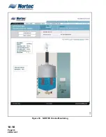
Страница 64: ...10 10 Page 56 2008 10 01 Figure 30 NORTEC OnLine Monitoring ...
Страница 71: ...10 20 Page 63 2008 10 01 10 20 SPECIFICATIONS ...
Страница 81: ...10 30 Page 73 2008 10 01 10 30 SUBMITTALS ...
Страница 86: ...10 30 Page 78 2008 10 01 Figure 2 Primary Line Voltage Wiring to Unit ...
Страница 87: ...10 30 Page 79 2008 10 01 Figure 3 Physical Data NHTC NHPC 005 030 ...
Страница 88: ...10 30 Page 80 2008 10 01 Figure 4 Physical Data NHTC NHPC 050 100 ...
Страница 89: ...10 30 Page 81 2008 10 01 Figure 5 Physical Data NHTC NHPC 150 200 ...
Страница 95: ...10 30 Page 87 2008 10 01 Figure 11 In Duct AHU Installation Without Mounting Frame Installation ...
Страница 96: ...10 30 Page 88 2008 10 01 Figure 12 In Duct AHU Installation With Mounting Frame Installation ...
Страница 97: ...10 30 Page 89 2008 10 01 Figure 13 Outside Duct Installation Without Mounting Frame Installation ...
Страница 98: ...10 30 Page 90 2008 10 01 Figure 13 In Duct AHU Installation With Mounting Frame Installation ...
Страница 99: ...10 30 Page 91 2008 10 01 Figure 14 Vertical Duct Installation Figure 15 Outside Duct Mounting Cover Plates ...
Страница 100: ...10 30 Page 92 2008 10 01 Figure 16 Atmospheric SAM e Adapter Dimensions ...
Страница 101: ...10 30 Page 93 2008 10 01 Figure 17 Atmospheric Steam Header and Adapter Configuration ...
Страница 102: ...10 30 Page 94 2008 10 01 Figure 18 Physical Data for Remote Mounted Blower Pack ...
Страница 103: ...10 30 Page 95 2008 10 01 Figure 19 Physical Data Units with Optional Built On Blower Packs ...
Страница 104: ...10 30 Page 96 2008 10 01 Figure 20 Physical Data Units with Optional Built On Blower Packs ...


