


10-10
Page 46
2008-10-01
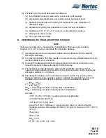
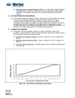
(2) NORTEC recommends the installation of a condensate drain on the steam inlet run
prior to entering the SAM-e.
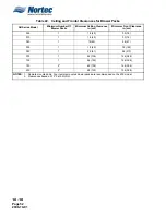
Table 16. Condensate Loss
E.
CORRECT CHOICE OF PRODUCT APPLICATIONS (WITHIN SAM-e)
(1) The SAM-e has been designed exclusively for use in building ventilation duct systems,
where manufacturing, processing and hi-tech activities are conducted. Applications that
do not conform to the design parameters are not recommended and will be at the
user’s own risk. NORTEC produces a wide range of different humidification systems to
suit virtually all normal applications, and will be happy to recommend the most
appropriate system to suit each particular requirements.
F.
SAM-e DIMENSIONS
(1) Dimensions for the SAM-e and mini SAM-e can be found in Figure 6 and Figure 7 in
Chapter 10-30.
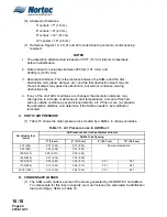
G. SAM-e HEADER SELECTION
(1) NORTEC offers different ranges of manifolds to cover capacities and duct sizes. The
absorption distance and capacity required will determine the center to center spacing
between each steam tube on the header. There are four options: 3" (7.6 cm),
6" (15.2 cm), 9" (22.9 cm) or 12" (30.5 cm). The smaller the spacing, the more tubes
the header can accommodate, thus giving a better absorption distance and greater
capacity. (See Tables 17 to 20.)
(2) The header remains the same for in-duct or outside duct mounting, for atmospheric
steam, and for vertical or horizontal flow applications. (See Figure 23.)
(3) Atmospheric manifolds with a capacity over 801 lbs/hr (362 kg/hr) will include a second
steam inlet on the header. Consult factory submittal drawings for specific details.
(4) Select the header part number associated with your duct or air handling unit’s width.
For example, if the duct width is 80" (198.11 cm), select part number 150-3279 for
3" (7.6 cm) center-to-center spacing.
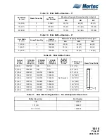
H.
SAM-e STEAM TUBE SELECTION
(1) Constructed of 1.5" (3.81 cm) OD 304 stainless steel tubing, the steam tubes can
accommodate duct heights between 18" (45.72 cm) - 144" (365.76 cm) for in-duct
header mounting. For smaller duct applications, a mini SAM-e can accommodate sizes
starting at 12" (30.5 cm) wide x 8" (20.3 cm) high. (See Figure 20.) Each steam tube
has a different amount of stainless steel nozzles to evenly disperse steam into the duct
or air handling unit. The nozzles take the steam from the center of the tube, eliminating
any need for jacket heating, and a temperature switch. All the accumulating
condensate is drained vertically down to the main header, and then out the condensate
drain. NORTEC’s unique ‘slip in’ installation method makes for a very quick and
effortless assembly. (See Figure 24.)
Air Velocity fpm (cm/s)
Condensate Losses (% of Maximum Capacity)
55°F 70°F
500 (255)
15%
12%
1000 (510)
20%
15%
NOTE:
These values may increase or decrease due to many unknown conditions or variables. This is only a guideline.
Содержание NHPC
Страница 1: ...2538144 B NH Series NHTC NHPC ELECTRODE STEAM HUMIDIFIER Engineering Manual TM ...
Страница 9: ...10 00 Page 1 2008 10 01 10 00 INTRODUCTION ...
Страница 10: ...10 00 Page 2 2008 10 01 Figure 1 NHTC ...
Страница 13: ...10 00 Page 5 2008 10 01 Figure 2 Optimum Boiling Time Figure 3 Conductivity ...
Страница 18: ...10 00 Page 10 2008 10 01 Figure 6 Typical NHRS Installation Sheet 1 of 2 ...
Страница 19: ...10 00 Page 11 2008 10 01 Figure 7 Typical NHRS Installation Sheet 2 of 2 ...
Страница 20: ...10 10 Page 12 2008 10 01 10 10 HUMIDITY STEAM ABSORPTION AND DISTRIBUTION ...
Страница 35: ...10 10 Page 27 2008 10 01 Figure 2 Psychrometric Chart ...
Страница 47: ...10 10 Page 39 2008 10 01 Figure 13 Humidification Distance Nomogram Figure 12 Cutting Duct For Mounting ...
Страница 58: ...10 10 Page 50 2008 10 01 Figure 26 Typical SAM e Installation for Atmospheric Steam Applications ...
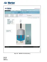
Страница 64: ...10 10 Page 56 2008 10 01 Figure 30 NORTEC OnLine Monitoring ...
Страница 71: ...10 20 Page 63 2008 10 01 10 20 SPECIFICATIONS ...
Страница 81: ...10 30 Page 73 2008 10 01 10 30 SUBMITTALS ...
Страница 86: ...10 30 Page 78 2008 10 01 Figure 2 Primary Line Voltage Wiring to Unit ...
Страница 87: ...10 30 Page 79 2008 10 01 Figure 3 Physical Data NHTC NHPC 005 030 ...
Страница 88: ...10 30 Page 80 2008 10 01 Figure 4 Physical Data NHTC NHPC 050 100 ...
Страница 89: ...10 30 Page 81 2008 10 01 Figure 5 Physical Data NHTC NHPC 150 200 ...
Страница 95: ...10 30 Page 87 2008 10 01 Figure 11 In Duct AHU Installation Without Mounting Frame Installation ...
Страница 96: ...10 30 Page 88 2008 10 01 Figure 12 In Duct AHU Installation With Mounting Frame Installation ...
Страница 97: ...10 30 Page 89 2008 10 01 Figure 13 Outside Duct Installation Without Mounting Frame Installation ...
Страница 98: ...10 30 Page 90 2008 10 01 Figure 13 In Duct AHU Installation With Mounting Frame Installation ...
Страница 99: ...10 30 Page 91 2008 10 01 Figure 14 Vertical Duct Installation Figure 15 Outside Duct Mounting Cover Plates ...
Страница 100: ...10 30 Page 92 2008 10 01 Figure 16 Atmospheric SAM e Adapter Dimensions ...
Страница 101: ...10 30 Page 93 2008 10 01 Figure 17 Atmospheric Steam Header and Adapter Configuration ...
Страница 102: ...10 30 Page 94 2008 10 01 Figure 18 Physical Data for Remote Mounted Blower Pack ...
Страница 103: ...10 30 Page 95 2008 10 01 Figure 19 Physical Data Units with Optional Built On Blower Packs ...
Страница 104: ...10 30 Page 96 2008 10 01 Figure 20 Physical Data Units with Optional Built On Blower Packs ...


