


10-10
Page 33
2008-10-01
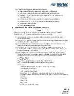
Table 11. Steam Line Material
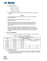
Table 12. Recommended Material and Size for Steam Run
Table 13. Recommended Condensate Line at Distributor(s)
Steam Hose
Copper Tube
Stainless Steel Tube
Short run < 10 feet (3 m)
yes
yes
yes
Long run > 10 feet (3 m)
yes
yes
NOTE:
Steel, Iron and aluminum tubing or pipe must not be used for the steam distribution lines with these humidifiers.
Plastic tubing and pipe also must not be used for steam distribution lines.
Load
Steam Run
Steam Line
Material
Steam Line
Description
lb/hr
kg/hr
ft
m
0-30
0-13
0-10
0-3
Copper Tube
¾" MED-L
Tubing
(
f
" OD)
0-30
0-13
10 +
3 +
Copper Tube
1"MED-L Tubing
(1
c
" OD)
0-30
0-13
0-10
0-3
Stainless Steel
Tube
f
" Tube x
0.049" thick.
0-30
0-13
10 +
3 +
Stainless Steel
Tube
1
c
"Tube x
0.049” thick.
30-100
13-45
0-20
0-6
Copper Tube
1½" MED-L
Tubing (1
e
"
OD)
30-100
13-45
20 +
6 +
Copper Tube
2"MED-L Tubing
(2
c
"OD)
30-100
13-45
0-20
0-6
Stainless Steel
Tube
1¾" Tube x
0.065" thick.
30-100
13-45
20 +
6 +
Stainless Steel
Tube
2" Tube x
0.065" thick.
NOTE:
Options shown in a
bold-italic font
require that reducers be used at both ends. These extra large sizes are to
allow for better condensation removal in long steam runs. These sizes do not permit the use of hose couplings
to connect either humidifier or distributors.
NOTE:
Insulate all copper or stainless steel steam lines with minimum one inch high temperature insulation.
Dispersion Method
Condensate Hose
Copper Tube
Stainless Steel Tube
1 x Steam Distributor
d
" NORTEC 1328840
¼" MED-L Tubing (
d
"
OD)
d
" Tube 0.049" thick.
3 x Steam Distributor*
d
" NORTEC 1328840
½" MED-L Tubing
(
f
" OD)
e
" Tube 0.049" thick
NOTE:
When using more than one distributor, the condensate line should be trapped before it is joined together.
Содержание NHPC
Страница 1: ...2538144 B NH Series NHTC NHPC ELECTRODE STEAM HUMIDIFIER Engineering Manual TM ...
Страница 9: ...10 00 Page 1 2008 10 01 10 00 INTRODUCTION ...
Страница 10: ...10 00 Page 2 2008 10 01 Figure 1 NHTC ...
Страница 13: ...10 00 Page 5 2008 10 01 Figure 2 Optimum Boiling Time Figure 3 Conductivity ...
Страница 18: ...10 00 Page 10 2008 10 01 Figure 6 Typical NHRS Installation Sheet 1 of 2 ...
Страница 19: ...10 00 Page 11 2008 10 01 Figure 7 Typical NHRS Installation Sheet 2 of 2 ...
Страница 20: ...10 10 Page 12 2008 10 01 10 10 HUMIDITY STEAM ABSORPTION AND DISTRIBUTION ...
Страница 35: ...10 10 Page 27 2008 10 01 Figure 2 Psychrometric Chart ...
Страница 47: ...10 10 Page 39 2008 10 01 Figure 13 Humidification Distance Nomogram Figure 12 Cutting Duct For Mounting ...
Страница 58: ...10 10 Page 50 2008 10 01 Figure 26 Typical SAM e Installation for Atmospheric Steam Applications ...
Страница 64: ...10 10 Page 56 2008 10 01 Figure 30 NORTEC OnLine Monitoring ...
Страница 71: ...10 20 Page 63 2008 10 01 10 20 SPECIFICATIONS ...
Страница 81: ...10 30 Page 73 2008 10 01 10 30 SUBMITTALS ...
Страница 86: ...10 30 Page 78 2008 10 01 Figure 2 Primary Line Voltage Wiring to Unit ...
Страница 87: ...10 30 Page 79 2008 10 01 Figure 3 Physical Data NHTC NHPC 005 030 ...
Страница 88: ...10 30 Page 80 2008 10 01 Figure 4 Physical Data NHTC NHPC 050 100 ...
Страница 89: ...10 30 Page 81 2008 10 01 Figure 5 Physical Data NHTC NHPC 150 200 ...
Страница 95: ...10 30 Page 87 2008 10 01 Figure 11 In Duct AHU Installation Without Mounting Frame Installation ...
Страница 96: ...10 30 Page 88 2008 10 01 Figure 12 In Duct AHU Installation With Mounting Frame Installation ...
Страница 97: ...10 30 Page 89 2008 10 01 Figure 13 Outside Duct Installation Without Mounting Frame Installation ...
Страница 98: ...10 30 Page 90 2008 10 01 Figure 13 In Duct AHU Installation With Mounting Frame Installation ...
Страница 99: ...10 30 Page 91 2008 10 01 Figure 14 Vertical Duct Installation Figure 15 Outside Duct Mounting Cover Plates ...
Страница 100: ...10 30 Page 92 2008 10 01 Figure 16 Atmospheric SAM e Adapter Dimensions ...
Страница 101: ...10 30 Page 93 2008 10 01 Figure 17 Atmospheric Steam Header and Adapter Configuration ...
Страница 102: ...10 30 Page 94 2008 10 01 Figure 18 Physical Data for Remote Mounted Blower Pack ...
Страница 103: ...10 30 Page 95 2008 10 01 Figure 19 Physical Data Units with Optional Built On Blower Packs ...
Страница 104: ...10 30 Page 96 2008 10 01 Figure 20 Physical Data Units with Optional Built On Blower Packs ...


