


10-20
Page 68
2008-10-01
e
Channel 2 Set point – Control channel 2 setpoint for relative humidity in
space 0-100% (read/write).
f
System Demand – Indicates humidifier system demand based on input
signal calculations 0-100% (read).
g
Demand/rh_Configuration Parameter – Configures humidifier to accept
demand or %rh signal(s) (read/write).
h
Remote fault Indication – System fault indication and alarm status (read).
i
Network Sensors – Allows network-enabled sensing or control (read/write).
j
Remote Disable – Provides remote humidifier enable/disable system
control. (read/write).
k
Remote Service Indication – Provides remote humidifier service
indication (read).
l
Remote Status Indication – Provides remote humidifier on/standby
system status indication (read).
(3) Remote Monitoring And Control Options (NHTC and NHTC OUTDOOR only)
Reference: Section 15900 - Building Controls and Automation
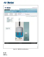
(a) NORTEC OnLine web based monitoring and control from any location with Internet
access, using standard Internet Explorer, version 6.0 or newer.
(b) NORTEC OnLine remote monitoring hardware using secure <DHCP Ethernet
Connection> or <Static IP Ethernet Connection> or <Dial-up Internet Connection>
or <GPRS wireless Internet Connection> Internet communication protocols.
(c) NORTEC OnLine Monitoring Service (NOMeS) with weekly humidifier examination
by factory direct technicians for first year, renewable/extendable up three
consecutive years.
(d) One additional year (third year), extended humidifier warranty when renewed/
extended for third year of NORTEC OnLine Monitoring Service (NOMeS).
(e) Packaged accessory, factory installed and ready for customer supplied <Ethernet>
or <Modem> communication connection.
(f)
Package will include the listed items in either paragraph (f) 1 through 17 or
paragraph (g) 1 through 7:
1
Internet accessible graphical representation of humidifier performance.
2
Remotely enable/disable humidifier.
3
Remotely adjust rh% set point(s), if equipped.
4
Remotely adjust ‘limited capacity’.
5
Automated e-mail advisories for scheduled service or abnormal conditions.
6
Up to three customer e-mail addresses available for automated e-mail
advisories.
7
Up to 50 incidents, of factory direct support and follow-up per humidifier.
8
First year of remote access includes factory direct monitoring.
9
Weekly checks by NORTEC OnLine factory technicians.
10 Remote factory diagnostics and programming capability.
Содержание NHPC
Страница 1: ...2538144 B NH Series NHTC NHPC ELECTRODE STEAM HUMIDIFIER Engineering Manual TM ...
Страница 9: ...10 00 Page 1 2008 10 01 10 00 INTRODUCTION ...
Страница 10: ...10 00 Page 2 2008 10 01 Figure 1 NHTC ...
Страница 13: ...10 00 Page 5 2008 10 01 Figure 2 Optimum Boiling Time Figure 3 Conductivity ...
Страница 18: ...10 00 Page 10 2008 10 01 Figure 6 Typical NHRS Installation Sheet 1 of 2 ...
Страница 19: ...10 00 Page 11 2008 10 01 Figure 7 Typical NHRS Installation Sheet 2 of 2 ...
Страница 20: ...10 10 Page 12 2008 10 01 10 10 HUMIDITY STEAM ABSORPTION AND DISTRIBUTION ...
Страница 35: ...10 10 Page 27 2008 10 01 Figure 2 Psychrometric Chart ...
Страница 47: ...10 10 Page 39 2008 10 01 Figure 13 Humidification Distance Nomogram Figure 12 Cutting Duct For Mounting ...
Страница 58: ...10 10 Page 50 2008 10 01 Figure 26 Typical SAM e Installation for Atmospheric Steam Applications ...
Страница 64: ...10 10 Page 56 2008 10 01 Figure 30 NORTEC OnLine Monitoring ...
Страница 71: ...10 20 Page 63 2008 10 01 10 20 SPECIFICATIONS ...
Страница 81: ...10 30 Page 73 2008 10 01 10 30 SUBMITTALS ...
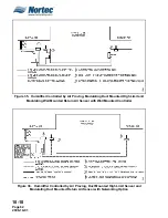
Страница 86: ...10 30 Page 78 2008 10 01 Figure 2 Primary Line Voltage Wiring to Unit ...
Страница 87: ...10 30 Page 79 2008 10 01 Figure 3 Physical Data NHTC NHPC 005 030 ...
Страница 88: ...10 30 Page 80 2008 10 01 Figure 4 Physical Data NHTC NHPC 050 100 ...
Страница 89: ...10 30 Page 81 2008 10 01 Figure 5 Physical Data NHTC NHPC 150 200 ...
Страница 95: ...10 30 Page 87 2008 10 01 Figure 11 In Duct AHU Installation Without Mounting Frame Installation ...
Страница 96: ...10 30 Page 88 2008 10 01 Figure 12 In Duct AHU Installation With Mounting Frame Installation ...
Страница 97: ...10 30 Page 89 2008 10 01 Figure 13 Outside Duct Installation Without Mounting Frame Installation ...
Страница 98: ...10 30 Page 90 2008 10 01 Figure 13 In Duct AHU Installation With Mounting Frame Installation ...
Страница 99: ...10 30 Page 91 2008 10 01 Figure 14 Vertical Duct Installation Figure 15 Outside Duct Mounting Cover Plates ...
Страница 100: ...10 30 Page 92 2008 10 01 Figure 16 Atmospheric SAM e Adapter Dimensions ...
Страница 101: ...10 30 Page 93 2008 10 01 Figure 17 Atmospheric Steam Header and Adapter Configuration ...
Страница 102: ...10 30 Page 94 2008 10 01 Figure 18 Physical Data for Remote Mounted Blower Pack ...
Страница 103: ...10 30 Page 95 2008 10 01 Figure 19 Physical Data Units with Optional Built On Blower Packs ...
Страница 104: ...10 30 Page 96 2008 10 01 Figure 20 Physical Data Units with Optional Built On Blower Packs ...


