background image


13 

| Installation


Location 

Mount to structural member or on surface capable of supporting the humidifier’s operating 
weight (see Figure 4: MES2 Dimensions and Weights). The humidifier may be set on its base but 
clearance must be provided for the drain line to be sloped adequately.  In general clearance is 
not required around the humidifier except for maintenance access and electrical and plumbing 
connections.   


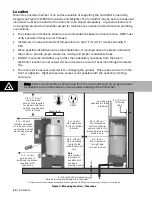
The clearance dimensions shown are recommendations based on best practice.  OEM must 
verify operation if they are not followed. 


Install only in areas with ambient temperature 41-104°F (5–40°C) relative humidity 5 - 
95%. 


When possible install below the steam distributor. If mounted above the steam distributor 
take care to provide proper steam line routing and proper condensate traps. 


DO NOT locate the humidifier any further then absolutely necessary from the steam 
distributor location as net output will be reduced as a result of heat loss through the steam 
line. 


The main service access required is for changing the cylinder.  This access can be from the 
front or right side.  Right side service access is not possible with the optional plumbing 
enclosure. 


* Dimensions are recommendations based on best practice. OEM must verify operation if they are not followed. 

Figure 9: Mounting Location / Clearance 

Note:

 Nortec recommends a vertical drop from the drain outlet and an air gap as close 

as possible to the drain outlet to insure proper draining of the humidifier.   

36 in. (92 cm)*

side clearance

for right side 

cylinder removal

only.

36

*

front clearance

for front cylinder

removal and/or for 

attached electronics

models only.

 in. (92 cm)

Mount level

As close as

possible to steam 

distributor

5-95%

0.5 in. (1.3 cm)*

top clearance

access hole required

for steam outlet and 

optional condensate 

return to fill cup.

8 in.  (20 cm)*

left side clearance

for removal of cover 

on attached closed
electronics models

only.

0 in. (0 cm) 

front clearance

for right side 

cylinder removal

0

0

side clearance

for front cylinder 

removal

 in. (  cm)

Note:

side cylinder

removal not 

possible with 
enclosed 
pluming option.

0 in.  (0 cm) 

access hole or 

additional clearance 

required for fill 

connection

0 in (0 cm) bottom clearance.

Access for properly sloped drain required.

0.2 (0.5 cm)*

for fill cup

tabs.

Содержание MES2

Страница 1: ...tion Manual Includes installation operation maintenance and troubleshooting information for the MES2 Electrode Steam humidifier 2554140 B 18 OCT 2010 Important Read and save these instructions This guide to be left with equipment ...

Страница 2: ...xcept to the extent required for installation or maintenance of recipient s equipment All references to the Nortec name should be taken as referring to WALTER MEIER LTD Liability Notice Nortec does not accept any liability for installations of humidity equipment installed by unqualified personnel or the use of parts components equipment that are not authorized or approved by Nortec Copyright Notic...

Страница 3: ...ing 16 Steam Lines and Condensate Returns 19 Primary Voltage Wiring 20 Control Wiring 21 Modbus Wiring 22 MES2 Installation Checklist 23 Operation 24 User Interface 25 Humidifier Configuration 27 Modbus Configuration 30 Start Up Procedure 31 Maintenance and Servicing 32 Required Maintenance 36 Extended Shutdown 37 Maintenance Checklist 39 Troubleshooting 41 General Troubleshooting 43 MES2 Faults 4...

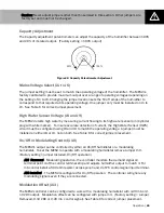
Страница 4: ...ocal electrical code in location where the humidifier will finally be operated CAUTION Plumbing Drain water from humidifier can be very hot Do not drain to public sink All plumbing work should be in accordance with local plumbing code in location where the humidifier will finally be operated CAUTION Installation Do not mount on hot surfaces Do not mount in area where freezing can occur Do not moun...

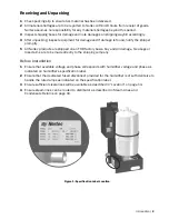
Страница 5: ... are shipped on an FOB factory basis Any and all damage breakage or loss claims are to be made directly to the shipping company Before Installation 1 Ensure that available voltage and phase corresponds with humidifier voltage and phase as indicated on humidifier s specification label 2 Ensure that the dedicated fused disconnect provided for the humidifier is of sufficient size to handle the rated ...

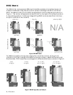
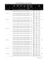
Страница 6: ... Voltage Wiring PVW model provides 8 feet of primary wiring for connection to the contactor Figure 2 MES2 Models The MES2 is available in 6 capacities ranging from 5 to 30 lb hr 2 3 to 13 6 kg hr for operation on a range of voltages and phases as outlined in Table 1 MES2 Part Numbers and Electrical Data The 6 capacities are packaged in 4 different cabinet sizes as shown in Figure 3 Figure 3 MES2 C...

Страница 7: ...0311 2550312 2550313 2550314 309 480 11 1 15 600 8 9 15 3 2550315 2550316 2550317 2550318 2550319 303 208 14 2 20 240 12 8 20 2550320 2550321 2550322 2550323 2550324 311 380 7 7 15 2550325 2550326 2550327 2550328 2550329 311 480 6 4 15 600 5 1 15 20 9 1 1 2550340 2550341 2550342 2550343 2550344 321 208 32 7 50 6 8 240 29 6 45 277 24 5 35 2550345 2550346 2550347 2550348 2550349 305 380 17 9 30 2550...

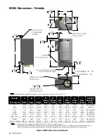
Страница 8: ...0 11 4 13 6 10 3 26 2 9 8 24 9 20 7 52 6 5 5 14 4 9 12 5 2 2 5 6 11 6 29 5 6 8 17 3 5 2 13 2 20 2 43 2 9 5 20 0 Note Steam Outlet is not centered on MES2 5 10 lb hr 2 3 4 5 kg hr models Weights given for MES2 with enclosed electronics and optional plumbing enclosure Full Weight is weight with cylinder full of water Full weight may exceed this value at end of cylinder life depending on the amount o...

Страница 9: ...lation and operation Table 2 Options and Accessories Option Accessory Used For Modbus Interface Controlling humidifier operation via Modbus See Modbus Wiring on page 21 and Modbus Configuration on page 27 Enclosed Plumbing See above Steam Distributors Adding steam into air ducts On Off or Modulating Control Humidistats Controlling the output of the humidifier based on sensed RH Air Proving Switch ...

Страница 10: ...tion Terminals Ground Clamp Bracket Remote Electrical Steam Outlet Condensate Return Fill Cup Drain Valve Drain Outlet Drain Canal Fill Valve Cylinder Cylinder Plug High Water Sensor Plug Fill Inlet Plumbing Enclosure Optional Plumbing Door Optional Cylinder Tie Wrap Drain Pan Status Lights Current Sensor Capacity Adjustment Potentiometer ...

Страница 11: ...rain Drain Valve Drains water from humidifier Control Board Controls all functions of the humidifier s operation and provides input and output connections to humidifier components Electrical Cover Covers the control board and wiring on MES2 models with closed electrical CE Fill Cup Provides an air gap for backflow prevention Fill Inlet 1 8 NPT brass fitting for connecting supply water to the humid...

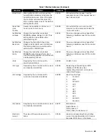
Страница 12: ...nal 1 and 2 is closed the humidifier assumes 100 demand closes the power relay on the control board and measures the current flowing through the power wire routed through the control board s current sensor If it is configured for modulating operation it waits for a demand signal and for the safety loop between terminal 1 and 2 to be closed From Contactor To Contactor 24 VAC Power Relay Control Boa...

Страница 13: ...e of 4 flashes Drains As steam is produced minerals are left behind increasing the conductivity of the water The MES2 s patented auto adaptive cycle will monitor the water conductivity and perform drains to maintain the water at optimal conductivity for peak performance The auto adaptive cycle provides the longest cylinder life in combination with keeping the tightest control and most efficient us...

Страница 14: ...tion Installation 12 Typical MES2 Installation 13 Location 14 Mounting 15 Plumbing 16 Steam Lines and Condensate Returns 19 Primary Voltage Wiring 20 Control Wiring 21 Modbus Wiring 22 MES2 Installation Checklist ...

Страница 15: ... 2 in 5 cm min 1 ft 30 cm Support brackets Fuse O n O f f S a f e t y L o o p 2 4 V A C On Off Drain Switch 2 4 V A C C o n t a c t o r E n e r g i z e Power Relay L2 L1 Disconnect Contactor Current transformer Cylinder plug with white marker Note Single Phase Connection Shown 0 875 in 22 mm OD 1 8 in NPT Air gap recom mended Drain 7 8 in Min Cold Potable Water 30 80 PSIG Front side clearance requ...

Страница 16: ...ylinder This access can be from the front or right side Right side service access is not possible with the optional plumbing enclosure Dimensions are recommendations based on best practice OEM must verify operation if they are not followed Figure 9 Mounting Location Clearance Note Nortec recommends a vertical drop from the drain outlet and an air gap as close as possible to the drain outlet to ins...

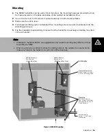
Страница 17: ... insure that the humidifier is securely and safely mounted in the air handler Figure 10 MES2 Mounting Note Installation methods shown are suggestions only actual mounting may differ and must be verified by OEM When mounting to a vertical member by drilling holes in the cabinet be careful not to make any holes in the bottom 1 in 2 5 cm of the drain pan MES2 Attached Electronics Back Mounted MES2 Re...

Страница 18: ...t located near the humidifier use a condensate pump rated for hot drain water such as Nortec s P N 1429527 For humidifiers installed in some cities including the City of Los Angeles A city approved spring loaded double ball CHECK VALVE must be installed by contractor on the potable water inlet to the humidifier Recommended valve manufacturer Watts Regulator Size 3 8 inlet and outlet Model 7 Each d...

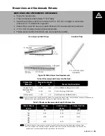
Страница 19: ...3 41 15 20 2 0 3 41 20 25 25 2 5 3 41 30 NOTE 1 Contact Nortec for information on possible losses of other steam line diameters used for longer runs 2 The use of steam line other then copper stainless steel tube or Nortec supplied steam line will void the warranty and may adversely affect the operation of the humidifier Steam Direction Steam Direction Steam Direction 2 in 5 cm 1 ft 30 cm 1ft 30 cm...

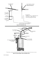
Страница 20: ... is greater Tee is same size as steam line Use a full size tee not a 90 degree elbow for vertical to horizontal transitions P Traps Use NORTEC 0 375 in condensate hose 1 4 in Med L copper tubing or 0 375 in stainless steel tubing Condensate drains must be sloped down Route to humidifier fill cup if possible 1 ft 30 cm before any bend 12 in 30 cm min radius Condensate trap Condensate line Connect s...

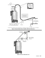
Страница 21: ...6 Common Steam Line Errors Steam line not sloped No condensate trap at vertical transition No drop to condensate trap 1ft 30 cm min before any bend 12 in 30 cm min radius Obstruction Use full size condensate tee at low point Slope lines up to T and immediately after it Hose will soften over time proper support Is necessary Support brackets 1 ft 30 cm min recommended To drain To drain 2 in 5 cm min...

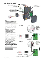
Страница 22: ...o cylinder plugs and tighten with 2mm allen wrench to11 in lb Ensure both plumbing cabinet and remote electrical bracket if present are grounded Use ground wires if required All wiring to be in accordance with national and local electrical codes 1 Phase L3 L2 L1 Disconnect Contactor Disconnect Contactor Cylinder plug with white marker Current transformer Current transformer Cylinder plug with whit...

Страница 23: ... Power Relay Contactor Mandatory Wiring 1 2 3 Optional Wiring 4 5 6 Use min 18 AWG and keep as short as possible 24 VAC to fuse connected to On Off Drain switch and to power relay 0 25 in spade connectors Ground wire from humidifier ground to air handler ground On Off Safety input 24 VAC input to point 2 of P3 Modulating control input 0 10 or 2 10 VDC to P5 J10 must be removed for modulation 500 o...

Страница 24: ...talled onto the MES2 control board to provide Modbus control of the MES2 In order for Modbus control to be active a jumper must be installed on J26 of the control board See Modbus Configuration on page 27 for information on configuring Modbus communication Figure 19 Modbus Wiring Note Regardless of selecting on off or modulating control method Nortec humidifiers must have a closed circuit across i...

Страница 25: ...Size Slope up min 2 in ft Slope down min 0 5 in ft Low point condensate traps No hose kinks Restrictions Type of Insulation if installed CONDENSATE LINE S P Trap min 6 in or duct press 2 in P Trap sufficient drop to ensure flow WATER LINE 1 2 in to within 4ft of unit Water pressure 30 80 psig DRAIN LINE Diameter Size ______________ Air gap within 3 ft of the unit CYLINDER Seated in drain valve and...

Страница 26: ...fier Configuration 26 Capacity Adjustment 26 Mains Voltage Select J1 to J6 26 High Water Sensor Voltage J8 and J9 26 On Off or Modulating Control J10 26 Modulation Offset J13 27 Ground Fault Interrupt GFI J15 27 Modbus Control J26 27 Modbus Configuration 27 Modbus Addresses 30 Start Up Procedure ...

Страница 27: ...ould be set to Off and the fused disconnect or breaker should be turned to Off Yellow LED Steady On When the yellow LED is steady on not flashing it indicates that the high water sensor has interrupted filling of the cylinder The LED is on for information only and unless it persists for an extended period of time it does not require any action On Off Drain Switch Turns humidifier On Off and drains...

Страница 28: ...d Jumpers Jumper Installed Removed J1 550 600 V No Affect J2 440 480 V No Affect J3 380 415 V No Affect J4 277V No Affect J5 220 240 V No Affect J6 200 208 V No Affect J8 HWS setting for 380 600 V No Affect J9 HWS setting for 200 277 V No Affect J10 On Off Operation Modulating Operation J13 2 10 VDC or 4 20 mA modulation 0 10 VDC or 0 20 mA modulation J15 GFI on power relay off during drain GFI of...

Страница 29: ...e A jumper must be installed on either J8 or J9 not on both See Table 6 for correct jumper placement On Off or Modulating Control J10 The MES2 s output can be controlled by either an On Off humidistat or a modulating humidistat To set the MES2 to operate with a modulating humidistat remove Jumper J10 Factory setting jumper Installed On Off operation J10 Removed Modulating operation the controller ...

Страница 30: ...uts received via Modbus and can be configured and queried using the Modbus interface Disable Self Test P11 2 3 On start up the MES2 performs a self test that activates all outputs briefly including the remote fault output To disable the self test the jumper installed on P11 pins 2 3 can be installed Modbus Configuration Contact Factory 1 866 NORTEC 1 Modbus Addresses The following table lists the ...

Страница 31: ...latile with a default value of 9600 B sec 40202 The value changes will only take effect following a hardware reset of the control board Set Modbus parity Change the humidifier controller s MODBUS parity Range is None Even Odd This setting shall be non volatile with a default setting of Even 40203 The value changes will only take effect following a hardware reset of the control board Units Required...

Страница 32: ...Humidifier state Describes the current state of the humidifier and it s I O s Contactor ON OFF Fill Valve ON OFF Drain Valve ON OFF 30107 Bit Allocation Note More than one bit can be active at any time Contactor on 1 Fill valve on 2 Drain valve on 4 Alarms The humidifier shall describe any faults Too long to fill Excess Current End of cylinder life No current 30108 Bit Allocation Note More than on...

Страница 33: ...emand for humidity and the security loop is closed the green humidifying LED on the front of the humidifier will light up the power relay on the control board will engage the fill valve will activate after a delay and the cylinder will slowly fill with water Note While the cylinder is filling with water there should be no water flowing down the drain If water is flowing down the drain it can indic...

Страница 34: ...ervicing 32 Required Maintenance 32 Cylinder Spent Fault 32 Replacement Cylinder 33 Removing the Cylinder 34 Drain Valve Cleaning 35 Installing the New Cylinder 36 Extended Shutdown 36 Starting After Extended Shutdown 37 MES2 Maintenance Checklist ...

Страница 35: ...igit model number on the label the humidifier s serial number and the humidifiers voltage Serial number and voltage are located on the specification label on the left side of the humidifier Figure 23 MES2 Cylinder Note Nortec recommends keeping a replacement cylinder in stock throughout the humidification season This will prevent possible downtime when the humidifier reports cylinder end of life C...

Страница 36: ...er loosen the hose clamp where the hose is connected to the cylinder 8 Using a small flat screwdriver press the tab on the cable tie holding the cylinder in place and pull the cable tie open 9 Tip the top of the cylinder forward to pivot it out of the steam hose When free of steam hose lift the cylinder out Figure 24 Cylinder Removal Warning Check to see if yellow service LED is flashing see Figur...

Страница 37: ...il cap on solenoid and remove the solenoid from the valve 5 Loosen brass nut holding actuator to plastic housing with a wrench and disassemble actuator 6 Clean actuator components and valve housing inlet port outlet port and cylinder port Put new o ring that was supplied with new cylinder into valve 7 Reassemble actuator making sure tapered end of spring is oriented as shown Figure 26 Tighten bras...

Страница 38: ... corresponding color coded cylinder pin Push down completely Connect high water sensor plug Spring loaded plugs should fit snuggly onto the cylinder pin Replace if they are loose or damaged 4 If enclosed plumbing option is installed replace the humidifier cover and secure with screw 5 Turn on power to humidifier with the external disconnect 6 Open supply water shut off valve 7 Turn the humidifier ...

Страница 39: ... valve 3 Turn on the power to the humidifier with the external disconnect 4 Turn the On Off Drain switch to the On position 5 Follow the start up procedure in the section titled Start Up Procedure on page 30 Note As long as the MES2 is powered it will automatically drain the cylinder when there has not been a call for humidity for an extended period of time This feature will reduce or prevent the ...

Страница 40: ...emoved cylinder Cylinder plug colors match cylinder dots Cylinder plugs snug and in good condition High Water Sensor plug snug and in good condition Steam hose attached Cover replaced water shut off valve open On Off Drain switch On Disconnect Closed SYSTEM CHECK Yellow Led flashing No Yes Flash Sequence See Troubleshooting Chapter for actions if yellow LED is flashing Primary power disconnect tur...

Страница 41: ...Maintenance and Servicing 38 ...

Страница 42: ...ting 40 Organization of Troubleshooting Chapter 40 Troubleshooting Requirements 41 General Troubleshooting 41 Humidifier 42 Steam Distributors 42 Modbus 42 MES2 Faults 43 LED Flash Sequence 43 Clearing a Fault 45 MES2 Wiring Diagram ...

Страница 43: ... wiring diagram is included at the end of this chapter for reference purposes When contacting your local representative or Nortec for troubleshooting assistance please ensure the serial number has been obtained for reference purposes NOTE Check if yellow service LED is flashing before turning off the humidifier to determine if a fault has occurred See Figure 20 on page 24 and Table 7 on page 43 Mo...

Страница 44: ...tting 24 VAC run signal 1c Check wiring and operation of On Off devices connected in series between output calling for humidity and point 2 of terminal P3 2 No demand signal If J10 removed for modulation 2 Check voltage between P5 and ground 25 of full scale signal must be present for humidifier to start 3 Not configured correctly for On Off or modulating control 3 Check that J10 on control board ...

Страница 45: ...ion instructions on page 16 7 Humidifier foaming and foam carried up steam line 7a Check if foaming caused by short cycling 7b Check if foaming caused by blocked or restricted drain 7c Check if steam line is causing back pressure and preventing proper filling Condensation in Air Handler 1 Installation clearances not observed 1 Refer to distributor installation manual for required clearances Reloca...

Страница 46: ...Corrective Action s 1 flash Excess Current Current has exceeded 130 of max 1 Drain blocked water over concentrated 1 Clean the drain line and drain valve 2 Drain solenoid not energized water over concentrated 2 Check and correct wiring to drain valve 3 Filling too fast fill valve damaged 3 Check fill rate and replace the fill valve if needed 4 Water supply too conductive 4a Contact Nortec represen...

Страница 47: ...mendation 6b Add 1 4 teaspoon of salt to fill cup and restart unit 3 flashes No Current High Water Water level at top of cylinder with no current 1 Primary wire not looped through current transformer 1 Open disconnect rewire primary wire through current transformer 2 1 phase of 3 phase supply blown 2 Check that all phases are energized 3 High water sensor plug is on an electrode pin 3 Install high...

Страница 48: ...f Primary Voltage Wiring PVW units which will come with all primary wiring to the cylinder and 10 of wiring to run the electrical back to the contactor Capacity adjust Calibration Do not ajust Control Signal 0 10 Vdc 2 10 Vdc 24 Vac Hot ON OFF Safties 24 VAC Common Modbus Interface Board 1509592 A B Common 1509591 Modulation Remove J10 for 0 10 VDC Remove Jumper J10 and place it on J13 for 2 10VDC...

Страница 49: ...Spare Parts 46 Exploded View and Spare Parts List ...

Страница 50: ...47 Spare Parts MES2 Spare Parts Figure 28 MES2 Spare Parts 1 10 9 7 2 11 13 5 14 15 3 4 6 17 12 8 16 ...

Страница 51: ... 1 2554074 1 2554075 1 1 2554076 1 1 7 Cylinder To order quote 3 digit number on existing cylinder or Ser No Model Voltage 8 Cyl Plug Black Marker 1510046 1 1 1 1 1 1 Cyl Plug Red Marker 1510047 1 1 1 1 1 1 Cyl Plug White Marker 1510048 1 1 1 1 1 1 Cyl Plug Yel Marker 1510049 1 Three phase humidifiers only 9 Tie Wrap Reusable 1513003 1 1 1 1 1 1 10 Fill Cup Assembly 2554069 1 2554070 1 2554071 1 1...

Страница 52: ...49 Warranty ...
Страница 53: ...all be attached to THE COMPANY until said products have been paid for in full and then said liability shall be limited to the original purchase price for the product Any further warranty must be in writing signed by an officer of THE COMPANY THE COMPANY s limited warranty on accessories not of the companies manufacture such as controls humidistats pumps etc is limited to the warranty of the origin...

Страница 54: ...octor Avenue Ogdensburg NY 13669 CANADA Walter Meier Climate Canada Ltd 2740 Fenton Road Ottawa Ontario K1T 3T7 TEL 1 866 NORTEC1 FAX 613 822 7964 EMAIL nortec waltermeier com WEBSITE www humidity com www norteconline com Certificate No 002419 ...

Отзывы: