


4
5
Alterations which serve the technological progress as well as errors excepted!
ORIGINAL MANUAL
NORSUP
WWW.NORSUP.EU
Alterations which serve the technological progress as well as errors excepted!
CONTROLLER & LOW SALT ELECTROLYSE UNIT TYPE NORSUPONE
CONTROLLER & LOW SALT ELECTROLYSE UNIT TYPE NORSUPONE
EN
2 INSTALLATION
A.2.1 DESCRIPTION
The NorsupOne kit can be delivered with
• Control box
• Relay box
A.2.2 CONTROL BOX
All the connectors are in this box, it allows you to
connect the probes and the relay box or boxes. Wifi,
ethernet, a 4 GB hard drive and 512 MB of memory are
installed by default. It offers total autonomy even
without internet with its own interface, onboard
software and all pool and spa automation.
Fig. 1: Control Box
A.2.3 RELAY BOX
It is made up of 8 numbers of 8A relays, and a
connector to connect it to the control box. These
relays can supply small equipment, metering pumps,
lights, dry contacts or supply power contactors for
larger equipment (filtration, heating, jet ...)
Fig. 2: Relay box
A.2.4 ELECTRICAL INSTALLATION AND WIRING
A 2.4.1 POWERING THE CONTROLLER
Two ports on top right of the controller are for the
powering (Neutral and Live)
Fig. 3: Powering of control box
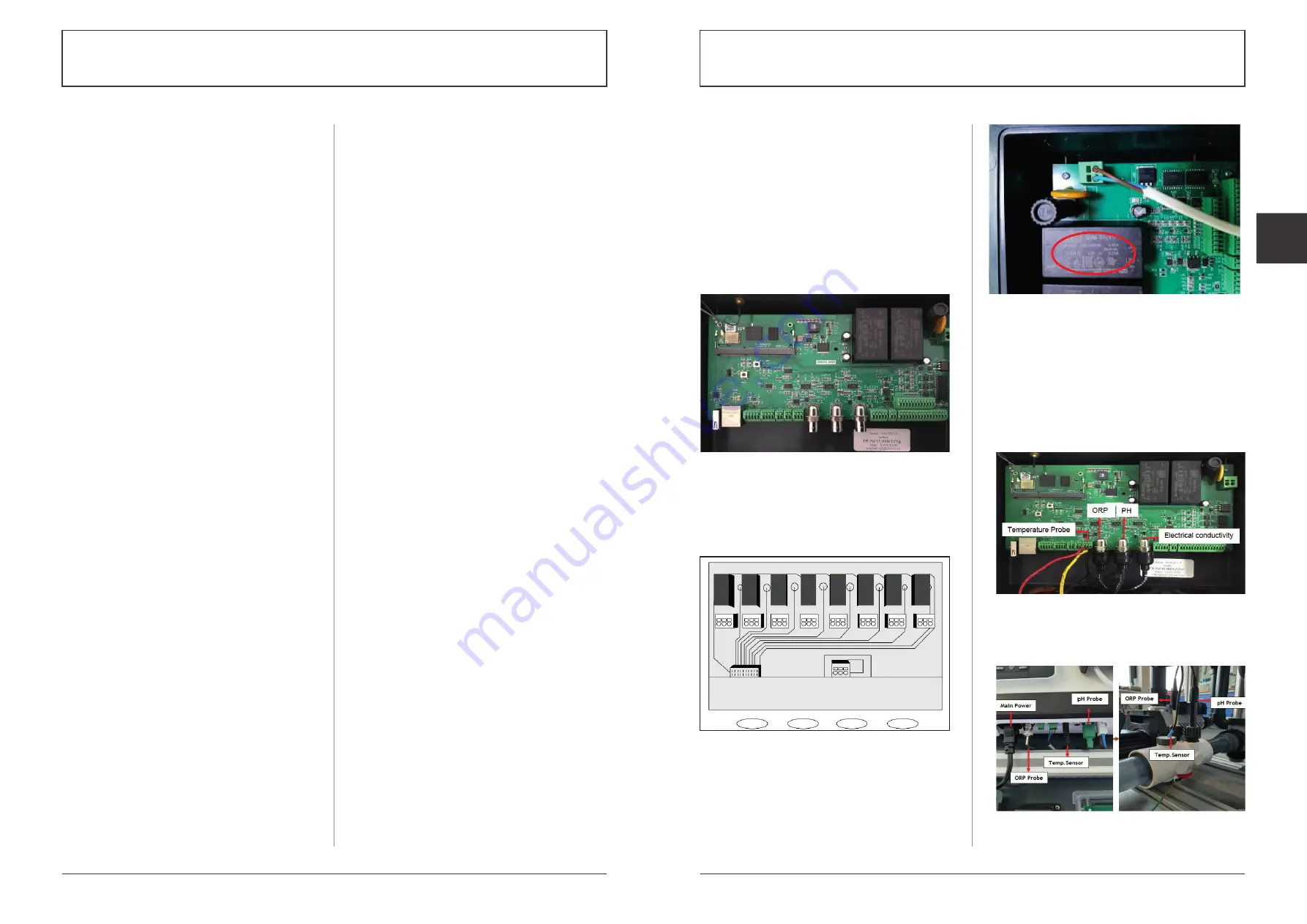
A.2.4.2 CONNECTIONS OF SENSORS TO
CONTROL BOX
Here we are connecting pH, ORP, Electrical
conductivity and temperature probe to control box
• Connect 3 wires of PT100 temperature sensor to the
U26 connector (Port 4 from right), red wire on the
left, the other 2 on the right whatever the direction.
• Connect flow detector on terminal block 7 to 12.
• Connect the BNC Connectors of ORP, pH and Electrical
conductivity probe respectively to the BNC input on
the control station as given in the below image.
Fig. 4: Connection of ORP, pH, EC and Temperature
sensor to the control box
You can also connect the sensors to Salt chlorinator
(If you are using) as shown in the figure below.
Fig. 5: Connection of ORP, pH, EC and Temperature
sensor in the accessory holder
A. HARDWARE INFORMATION
A.1 GENERAL INFORMATION
A.1.1 OVERVIEW
NorsupOne is an intelligent controller, equipped with
sensors and actuators around software specifically
developed for swimming pools and spas. NorsupOne
manages all types of treatment and water balance,
filtration, heating, roller shutters, lighting, led pulsed
lighting. A total of 15 actuators are possible.
The registration date corresponds to the creation of
the customer account on the NorsupOne registration
platform. The use of a NorsupOne home automation
controller implies the acceptance of the general
conditions of use.
When powering up, all relays light up to verify that all
of the signal wiring is correct. In case of doubt put all
devices in the OFF position on the user interface and
replug the relays, then carry out an ignition test of
each device and check that each relay triggers the
connected equipment.
During installation you must ensure that you comply
with the following points, to guarantee a correct
installation.
• A relay cannot control a power higher than 8A (1500 W)
• For higher powers, a power contactor is installed.
• Scrupulously respect the polarities of the Modbus
sensors, probes and buses.
• Respect the electrical standards for protection and
power of the circuit breakers.
• Connect an equipotential bonding to the hydraulic
circuit before filtration, in series with the earth
intended for the devices.
(If in doubt, contact your service representative or
your licensed electrician)
The mobile application of NorsupOne will enable the
installer and the customer to control devices and
sensors using IoT Flowers via IoT Flowers cloud service
and the web application enables the installer to
monitor the activities.
A.1.2 WARNINGS
Failure to follow these instructions may result in
serious injury or death
• The appliance is intended for swimming pools and
spas only the installation of the appliance must be
carried out by a person with proven and certain skills
in electricity and hydraulics
• Disconnect the appliance from the mains supply
before carrying out any work.
• All electrical connections must be made by a qualified
professional electrician and in accordance with the
standards in force in the country of installation.
• Make sure that the appliance is connected to an outlet
protected against short-circuits. The device must also
be supplied via an isolation transformer or a residual
current differential device (DDR) whose nominal
residual operating current does not exceed 30 mA.
• Ensure that children cannot play with the device. Keep
your hands and all foreign objects away from openings
and moving parts. In particular, make sure there is no
contact with electronic cards and power cables.
• Check that the supply voltage required by the
product corresponds to that of the distribution
network and that the supply cables are suitable for
the current supply of the product.
• Chemicals can cause internal and external burns. To
avoid death, serious injury and / or property damage:
Wear personal protective equipment (gloves, glasses,
mask ...) when servicing or maintaining this device.
This device must be installed in a sufficiently ventilated
room, protected from humidity and without contact
with splashes of water or other liquid.
• To reduce the risk of electric shock, do not use an
extension cord to connect the appliance to the
mains. Use a wall outlet.
• Read the instructions in this manual and the
instructions on the device carefully. Failure to comply
with the instructions and recommendations could
cause damage. This document must be given to any
end user, who will keep it in a safe place.
• This device can only be used by children under 18
years of age or by people with reduced physical,
sensory or mental capacities or lack of experience or
knowledge, only if they (if they) are properly
supervised (e) s or if instructions relating to the safe
use of the device have been given to them and if the
risks involved have been understood. Children should
not play with the device. Cleaning and user
maintenance must not be carried out by children
without supervision.
• If the power cable is damaged, it must be replaced
by the service provider originally installed, its after-
sales service or by persons of similar qualifications,
in order to avoid danger. Electric shock may occur.
ELECTRICAL CONNECTION STANDARDS
• F NF C 15-100
• GB BS7671:1992
• D DIN VDE 0100-702
• EW SIST HD 384-7-702.S2
• A ÖVE 8001-4-702
• H MSZ 2364-702:1994 / MSZ 10-533 1/1990
• E UNE 20460-7-702 1993, REBT ITC-BT-31 2002
• M MSA HD 384-7-702.S2
• IRL IS HD 384-7-702
• PL TS IEC 60364-7-702
• I CEI 64-8/7
• CZ CSN 33 2000 7-702
• LUX 384-7.702 S2
• SK STN 33 2000-7-702
• NL NEN 1010-7-702
• SLO SIST HD 384-7-702.S2
• P RSIUEE
• TR TS IEC 60364-7-702


