23
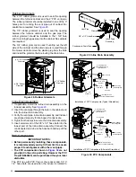
vent out thru the left or right side of the furnace cabinet.
See
. NOTE: If supplied with your
furnace, the NORDYNE PVC trap (664659) may be used
in place of the reducer and 1/2” X 1/2” hose barb
The 1/2” x 3/4” hose barb can be used to route the
condensate drain to the outside of the cabinet. It must
be installed from inside the cabinet with the threaded
end inserted thru the 1 1/16” hole. The Condensate drain
should be connected to the barbed end. Attach 1” PVC
drain line to the threaded end.
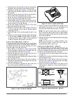
Typical Orientation
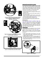
1. Install the PVC Tee vertically on the 2” vent pipe that is
extending out the side of the cabinet. Permanently bond
them together using appropriate primer and cement.
Refer to the typical orientation shown in
2. Install the reducer or PVC trap (if supplied) on the bottom
end of the PVC Tee. Permanently bond them together
using appropriate primer and cement.
3. Install the 1/2” x 1/2” hose barb on the 2” PVC reducer.
NOTE: Do not over tighten! Use an adequate amount of
Teflon tape on the threads. Do not use liquid sealants.
4. Verify all connections and joints for tight fit and proper
alignment with other vent pipes.
Alternate Orientation
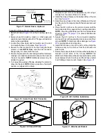
1. Install the 2” PVC Tee horizontally on the 2” vent pipe that
is extending out the side of the cabinet. Permanently bond
them together using appropriate primer and cement.
Refer to the alternate orientation shown in
2. Install the 2” PVC Elbow on the end of the 2” PVC Tee.
Permanently bond them together using appropriate
primer and cement.
3. Install the reducer or PVC trap (if supplied) on the bottom
end of the PVC Tee. Permanently bond them together
using appropriate primer and cement.
4. Install the 1/2” x 1/2” hose barb on the 2” PVC reducer.
NOTE: Do not over tighten! Use an adequate amount of
Teflon tape on the threads. Do not use liquid sealants.
5. Verify all connections and joints for tight fit and proper
alignment with other vent pipes.
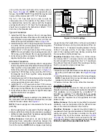
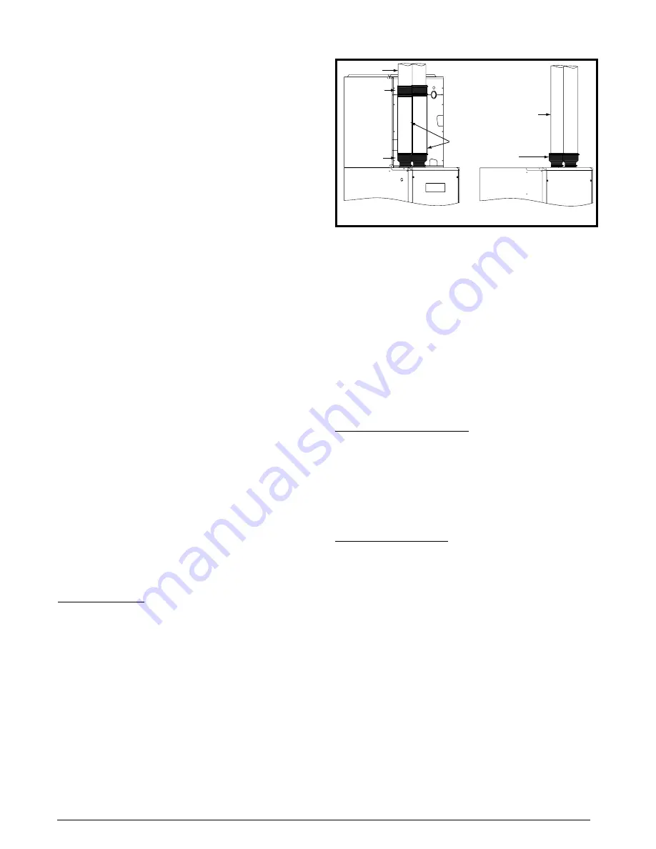
Vent Couplings
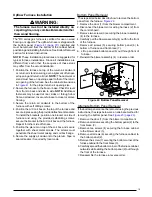
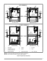
M4 series furnaces require couplings to be installed over
the combustion air finish flange and where the vent pipe
exits the furnace cabinet. See
.
NOTE: These couplings are not supplied in the *RL extra
parts bag.
• Each coupling must be secured to the finish flange
or
vent pipe with a hose clamp (if using neoprene couplings).
• Upflow furnaces require the 3” neoprene coupling clamps
to be installed above the coil box.
Upflow Furnaces: Combustion air and exhaust vent
piping must have removable connections between the
furnace flanges and vent pipes when installed vertically in
front of the coil box. NOTE: Both vent pipes must be long
enough to clear the height of the coil box when installed.
This allows for future servicing or maintenance of the coil.
Position the 2” x 3” neoprene coupling between the top
of the 2” vent pipe and the 3” vent pipe. Secure both
ends of the couplings with hose clamps, ensuring that
the connection is tight and leak free.
Downflow Furnaces: Since there is no coil box above
the furnace, both 3” vent pipes can be run vertically for
the entire length of the pipes from the 2” x 3” coupling to
the outdoors. Secure both ends of the couplings, ensuring
that the connection is tight and leak free.
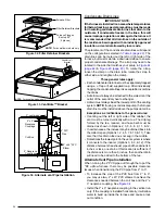
Filter Retainer Brackets
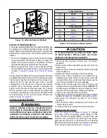
1. Bend the rear, right and left side furnace flanges upward
90° with a pair of wide duct pliers. See
2. Install three filter retainer brackets on the furnace flanges.
NOTE: Press down firmly to ensure brackets are tightly
installed on the furnace flanges.
3. Position a furnace filter on top of the filter brackets.
VentilAire™ Bracket
Ventilation must be provided for homes built to HUD
Manufactured Homes Safety and Construction Standards.
This ventilation can be supplied by a VentilAire™ III
(914098) or VentilAire™ IV (914229) fresh air supply
system. Alternate means for providing ventilation air
must meet the requirements of all applicable local and
federal codes.
Upflow Furnaces: the means for providing the required
ventilation must be incorporated into the upflow furnace
base or the return air ductwork to the furnace.
Downflow Furnaces: a special mounting bracket is
supplied with the furnace for installation of the VentilAire™
supply air system. The bracket is installed on the right
hand side at the top of the cabinet, as shown in
. The bracket can be secured to the unit
using the self-drilling screws supplied with the kit. Please
follow the instructions provided with the kit.
Figure 31
Figure 31. Vent Couplings
Coil Box
UPFLOW FURNACE
DOWNFLOW FURNACE
3” PVC Pipes
2” x 3”
Neoprene
Couplings
3” PVC
Pipes
3” Neoprene
Couplings
3” PVC Pipes
2” x 3”
Neoprene
Couplings
Содержание M4RC-072D-35C
Страница 47: ...47...

