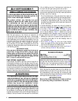
16
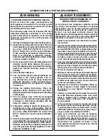
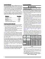
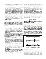
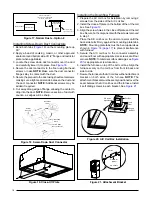
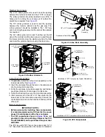
Figure 12
NOTES:
With reducer installed: Opening to duct is 10-1/4” x 13-1/4”.
With reducer removed: Opening to duct is 13-1/4” x 13-1/4”.
REDUCER
(See Notes)
FELT-SEAL
SPACERS
DUCT CONNECTOR TABS
FIBERGLASS
INSULATION
Figure 12. Duct Connector
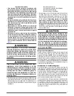
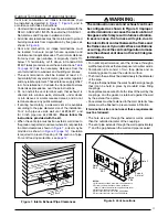
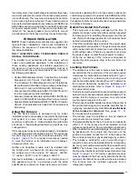
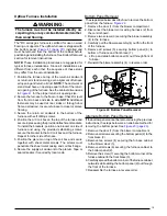
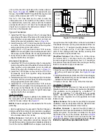
Figure 13
REAR WALL OF CLOSET OR ALCOVE
10”
13 1/4”
13 1/4”
Floor Cut-Out for
Duct Connector
FURNACE CABINET OUTLINE
FUEL
LINE
HOLE
ALT. FUEL
LINE HOLE
C
L
C
L
Figure 13.
Floor Cutout Dimensions
Downflow Furnace Installation
NOTE: These Installation procedures are suggested for
typical furnace installations. Since all installations are
different from each other, the sequence of instructions
may differ from the actual installation.
WARNING:
The furnace must not be installed directly on
carpeting, tile, or any combustible material other
than wood flooring.
The *RL series gas furnace is certified for use on wood
flooring or supports, but must be installed on a special
duct connector (
). This factory supplied accessory
must be installed in the floor cavity and attached to the
supply air duct before the downflow furnace is installed.
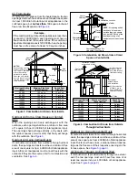
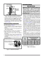
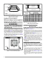
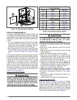
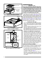
The depth of the floor cavity (shown as “X” in
)
will determine the duct connector size to use. Several
connector sizes are listed in
.
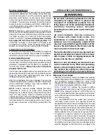
Table 3
If Floor Cavity
(“X”) is:
Duct Connector
Type & Part Number
Finger Tab
Screw Down
7/8” (22)
901987A
904008
2” (51)
901988A
904009
4-1/4” (108)
901989A
904010
6-1/4” (159)
901990A
904011
8-1/4” (210)
901991A
904012
10-1/4” (260)
901992A
904013
12-1/4” (311)
901993A
904014
NOTE: Dimensions shown as Inches (Millimeter)
Table 3.
Duct Connector Sizes
“X”
FLOOR OPENING
FLOOR CAVITY
SUPPLY AIR DUCT
Locating & Cutting Floor Openings
IMPORTANT NOTE:
Cut-outs in the floor, must be carefully located to
avoid misalignment of the furnace. To locate standard
ducts, see
.
1. Measure from the rear wall or alcove and mark the
centerline of the cut-out on the floor. Using the centerline
as a starting point, draw the rest of the duct cut-out to
the dimensions shown in
.
2. Cut out the floor opening to within 1” of the actual cutout
drawn.
3. Measure from the top of the floor down to the top of the
supply air duct to obtain the depth of the floor cavity.
NOTE: The depth of the floor cavity shown as “X” in
will determine the correct duct connector.
4. Determine which duct connector to use from the table.
5. Measure and drill gas hole and cut out for cooling coil
(if applicable).
Installing Finger Tabbed Duct Connectors
The standard duct connector is designed for use on ducts
12” in width. However ducts narrower than 12” may not
allow sufficient clearances for this type of installation.
See Narrow Duct Attachment for an alternate installation
method.
1. Center the duct connector in the floor opening with
bottom tabs resting on top of the supply air duct.
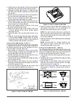
2. Mark the cut-out area on the supply air duct by tracing
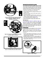
around the connector tabs (
) of
the duct connector.
3. Remove the duct connector and cut out the marked
area of the supply air duct 1/16” larger the actual cutout
drawn.
Содержание M4RC-072D-35C
Страница 47: ...47...

